Spinning machine

A spinning machine and frame technology, applied in the field of spinning machines, to achieve high cost performance, reduced longitudinal stroke, and reduced pressure loss

Active Publication Date: 2009-07-01
SAURER GERMANY GMBH & CO KG
View PDF6 Cites 3 Cited by
  • Summary
  • Abstract
  • Description
  • Claims
  • Application Information

AI Technical Summary

Problems solved by technology

[0010]The disadvantage of these looms is not only the arrangement of their supply and handling mechanisms inside the end frames, but also the positioning of the drives of the yarn traversing mechanisms in this area Inside
In other words, in the case of this type of textile machine, in order to continuously ensure that all stations are fully supplied with the negative pressure necessary for spinning, it is necessary to have a large cross-section of the air guide channel, thereby bringi

Method used


Image

  • Spinning machine
  • Spinning machine
  • Spinning machine

Examples


Embodiment Construction

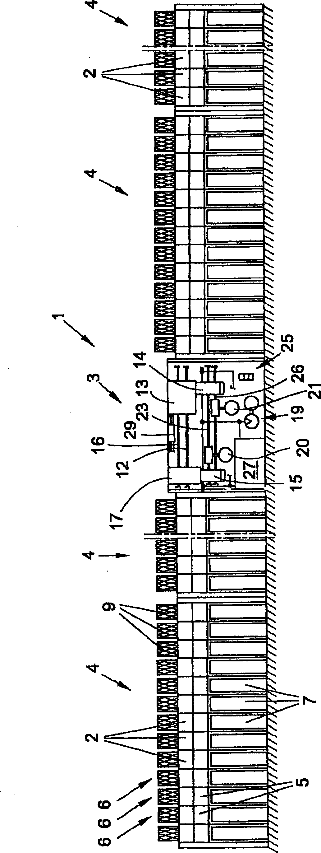
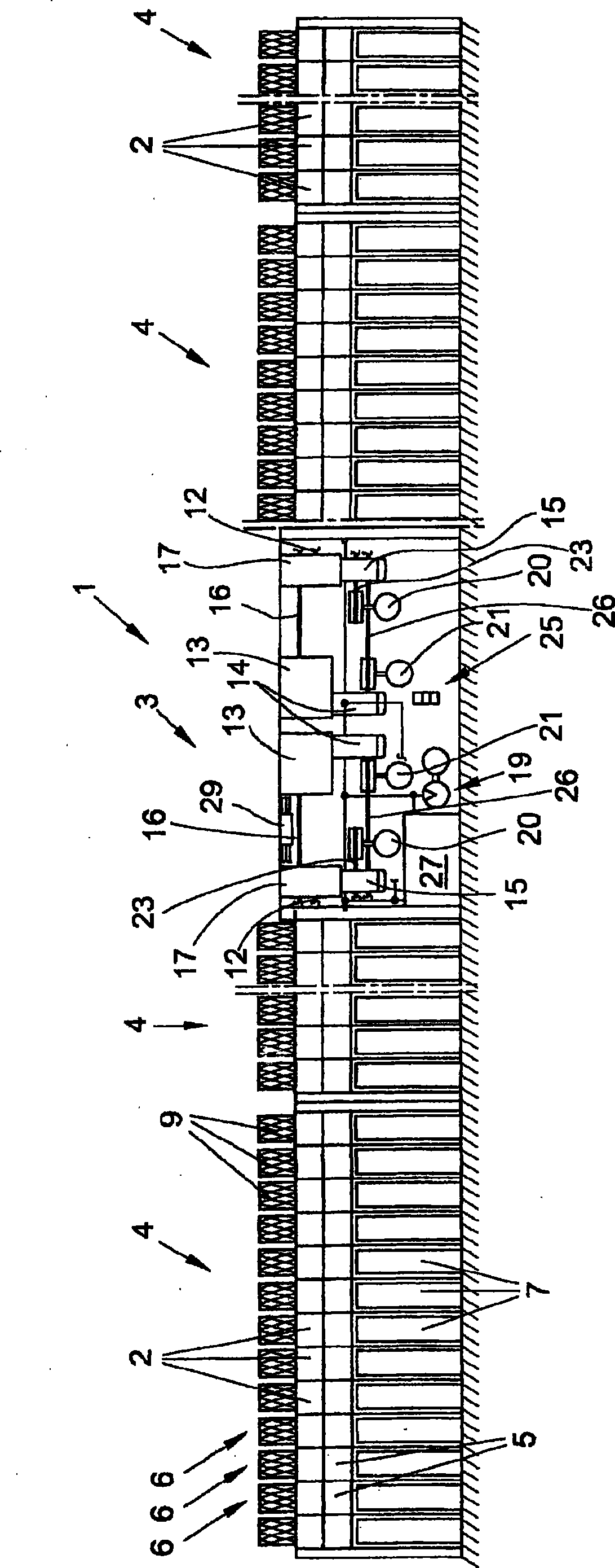
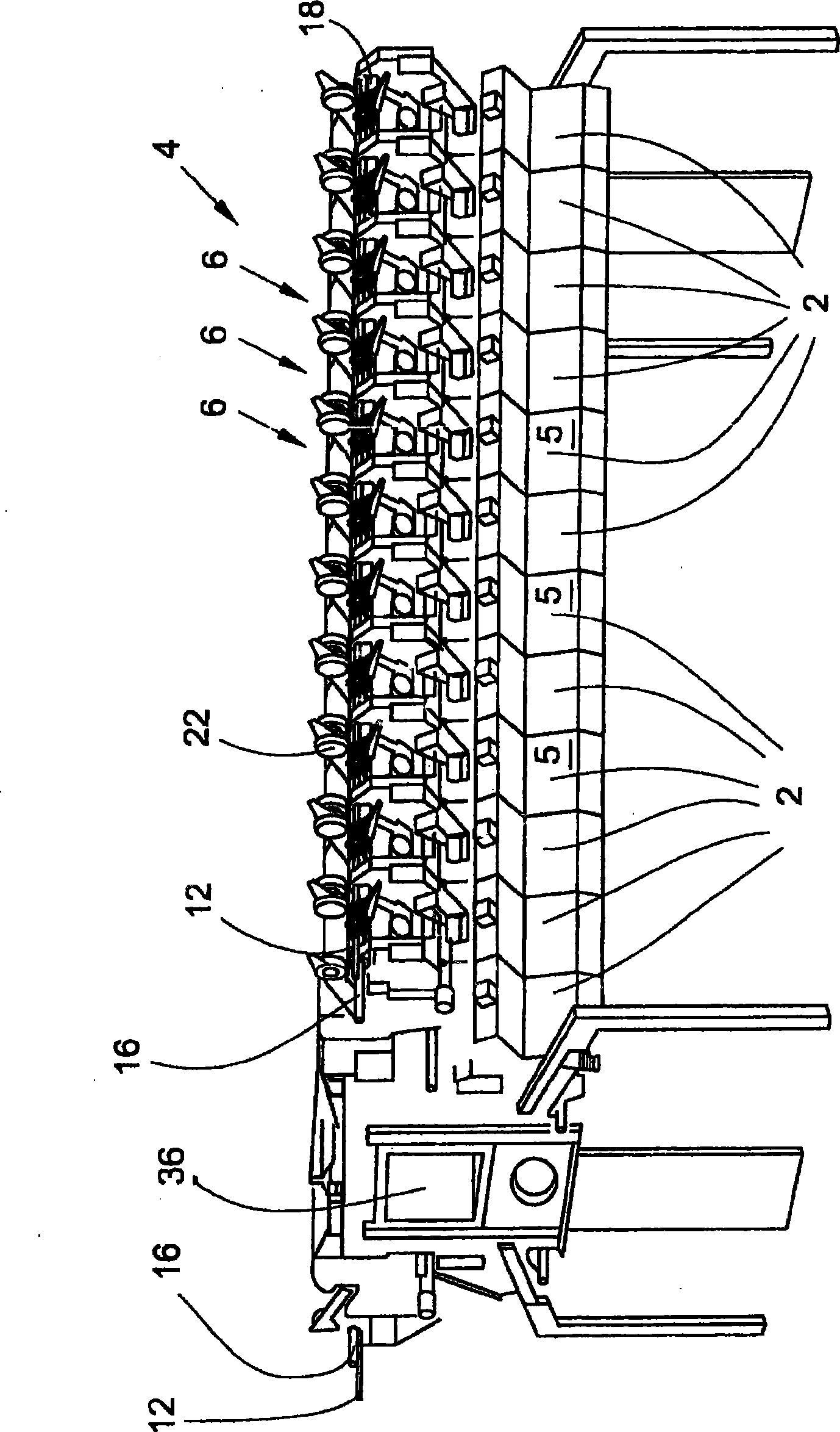
[0037] figure 1 An open-end rotor spinning machine 1 is shown as an embodiment of the spinning machine according to the invention, which has a plurality of work stations 2 and a frame 3 which is arranged approximately centrally between the work stations 2 . as in figure 1 described in and in figure 2 As further shown in , a plurality of these stations 2 are each combined into a part 4 which is generally a modular unit. The stations 2 themselves also each have an open-end spinning device 5 and a winding device 6 . As known, in the open-end spinning device 5, the fiber sliver fed in the spinning pot 7 is correspondingly spun into a yarn 8, which is then wound up on the winding device 6 as a cross-wrap Around the bobbin 9. The working mechanism of the workstation 2 is driven either by means of a so-called group drive or at least partially by means of an individual drive.

[0038] For example by means of such a group of drives actuated in Figure 4 with Figure 5 The yarn ...


PUM


Abstract

The invention relates to a spinning machine (1) which comprises a plurality of workstations (2), arranged in a row, that have respective spinning devices (5) for producing a thread (9) and a thread traversing device (10) for producing a cross-wound cone (8) that is rotatably received in a cone reel (22) of a cone winding device (6), a device (19) for supplying the negative pressure required for spinning and a drive (14) for the common traverse of the thread guides (11) of the thread traversing devices (10). The invention is characterized in that at least the drive (14) for the thread traversing devices (10) and the device (19) for supplying the negative pressure required for spinning are arranged in the only machine frame (3) of the spinning machine (1), the machine frame (3) being interposed between the workstations (2) of the spinning machine (1) in such a manner that the number of workstations (2) on every side of the machine frame (3) is at least 40% of the total of workstations.

Description

technical field [0001] The invention relates to a spinning machine according to the preamble of claim 1 . Background technique [0002] Different types of spinning machines are used in the textile industry and have been described, sometimes in great detail, in the patent literature. Such spinning machines are, for example, ring spinning machines, friction spinning machines, open-end spinning machines or open-end rotor spinning machines. Such textile machines usually have a large number of workstations arranged one behind the other and two frames arranged at the end, the so-called end frames. Here, at the stations of friction spinning machines, air spinning machines and open-end rotor spinning machines, the fiber sliver, which is preferably provided in the spinning pot, is spun into yarn and subsequently wound into cross laps Reel. For this purpose, the individual workstations also have spinning devices and winding devices accordingly. [0003] An open-end rotor spinning ...

Claims


Application Information

Patent Timeline
IPC IPC(8): D01H1/16
CPCD01H1/16
Inventor 托马斯·魏德拉尔夫·西韦特
Owner SAURER GERMANY GMBH & CO KG
Why Eureka
Try Eureka