
Upper cover of pressure electric cooker

A rice cooker and pressure technology, which is applied to pressure cookers and other directions, can solve the problems of large heat generation, high suction power and high cost, and achieve the effects of safe use, low cost and low heat generation.

Active Publication Date: 2009-07-08
MIDEA GRP CO LTD
View PDF5 Cites 10 Cited by
  • Summary
  • Abstract
  • Description
  • Claims
  • Application Information

AI Technical Summary

Problems solved by technology

Although this structure cancels the float valve, there is no problem of clogging the small hole of the float valve, but the suction force generated by the electromagnet needs to overcome its own elastic recovery force, which requires a relatively large suction force, resulting in high cost, and the electromagnet is in the process of working for a long time. In the suction state, the heat is large, and it is easy to fail and cause danger

Method used


Image

  • Upper cover of pressure electric cooker
  • Upper cover of pressure electric cooker
  • Upper cover of pressure electric cooker

Examples


Embodiment 1

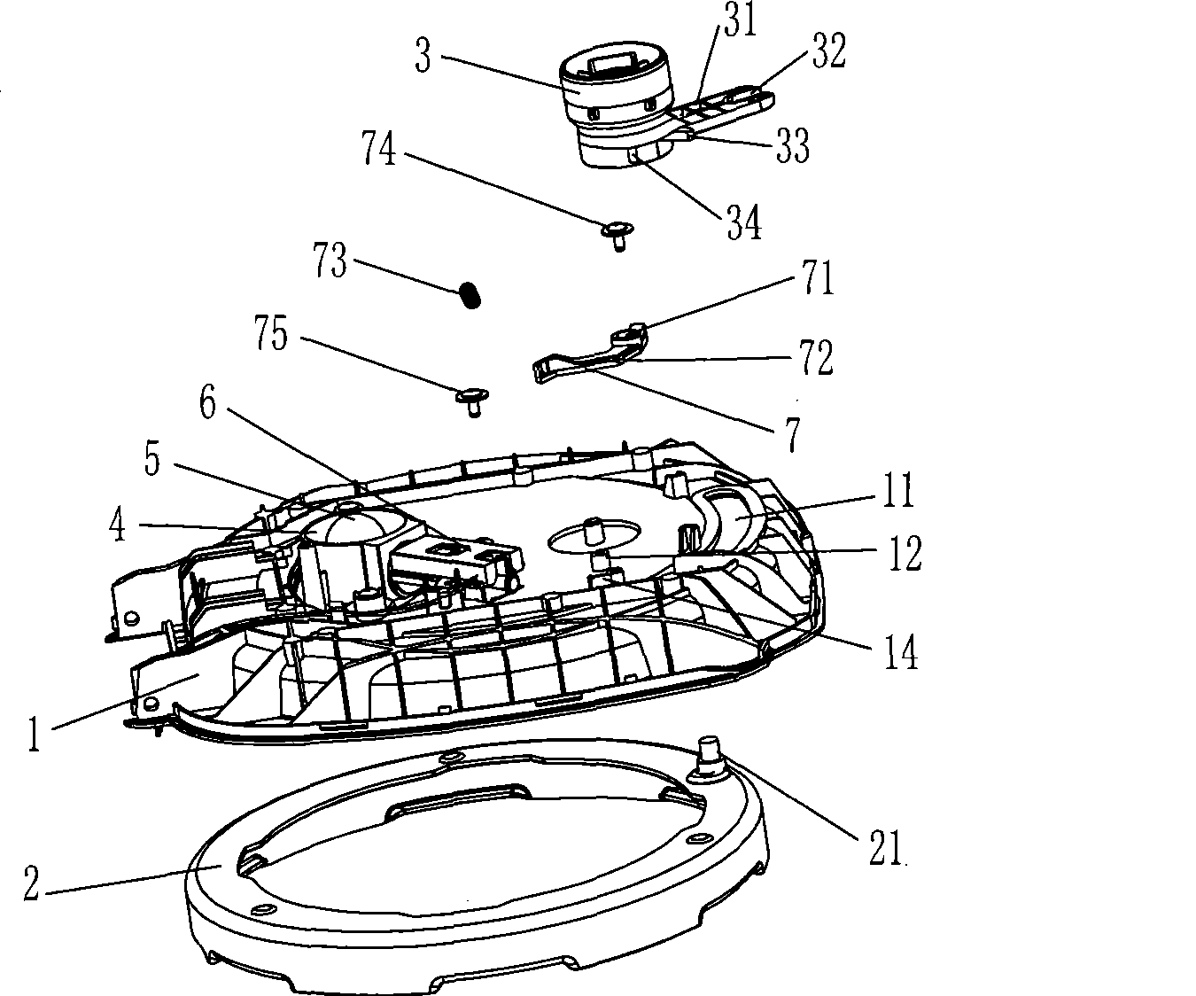
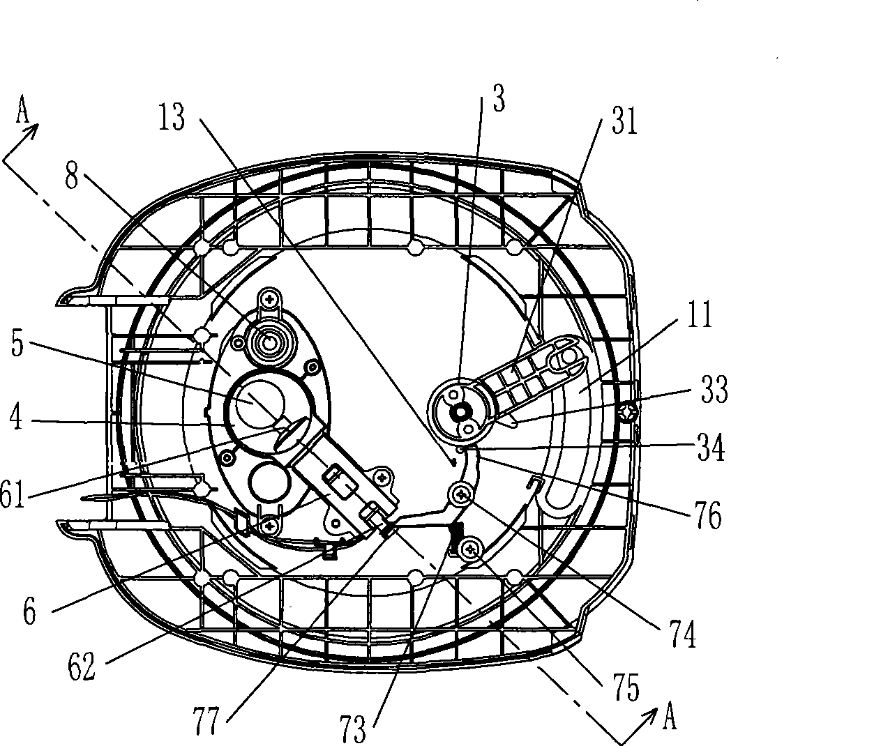
[0029] Such as figure 1 , figure 2 As shown, the upper cover of a pressure electric rice cooker in the present embodiment includes: an inner cover 1 hinged with the body of the pressure cooker (not shown in the figure), a lock catch 2 installed below the inner cover 1 and rotatable around its center, installed on The handle 3 on the top of the inner cover 1. The inner cover 1 is provided with an arc-shaped limit hole 11 along the circumference, and the corresponding limit hole 11 is provided with a limit pin 21 on the lock buckle 2. There is a pin hole 32 matched with the limit pin 21. When the user turns the rotary handle 3, the connecting rod 31 drives the limit pin 21 to slide along the limit hole 11, so that the lock catch 3 rotates, and the upper cover is locked. Transition between tight state and unlocked state.

[0030] Such as Figure 5 , 6 As shown, the inner cover 1 is provided with a pressure control mechanism composed of a steam channel 4 with a steam exhaust...

Embodiment 2

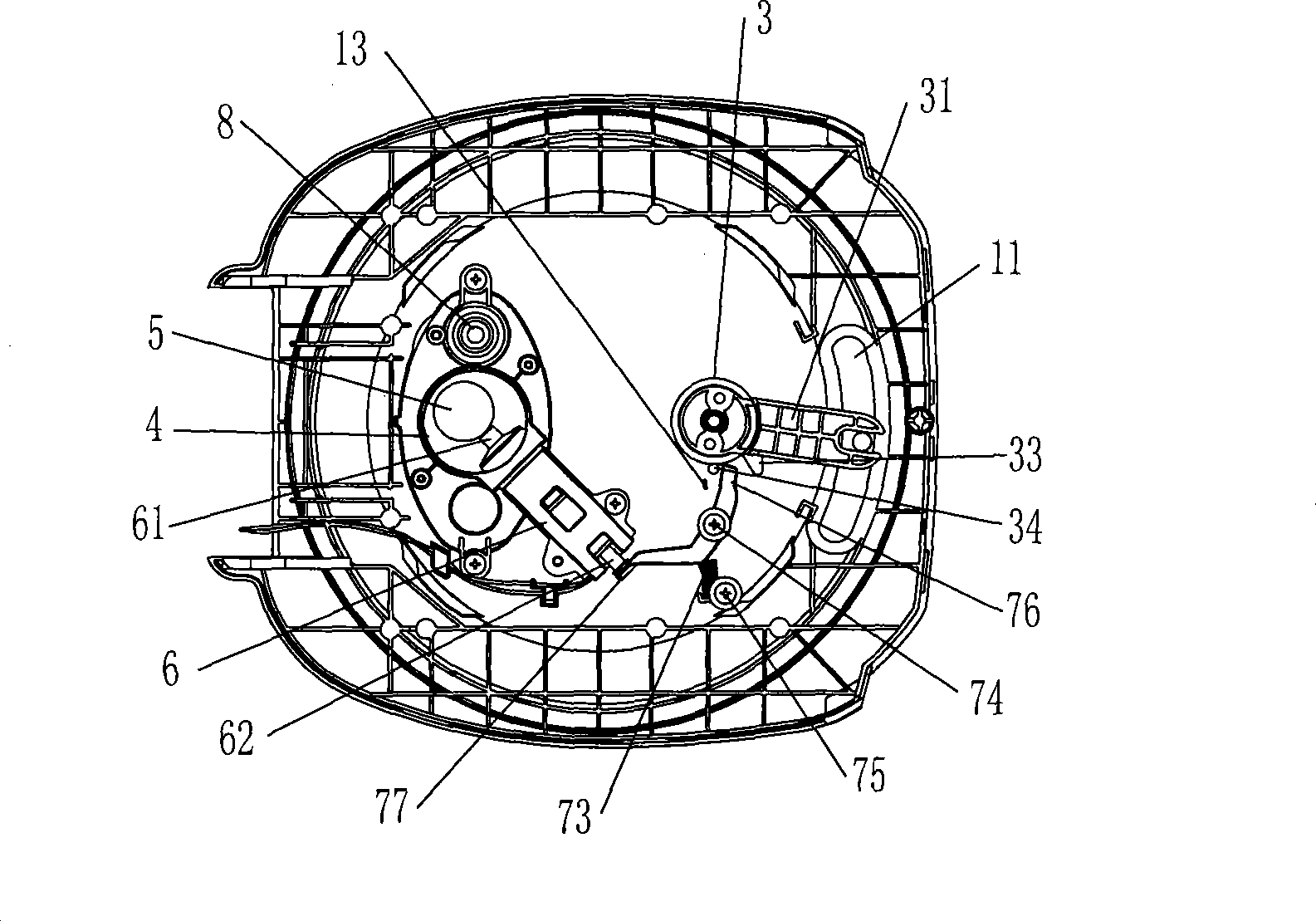
[0039] Such as Figure 7 , Figure 8 As shown, the difference between this embodiment and the first embodiment is that in the loam cake of the pressure rice cooker, the side of the handle 3 is provided with a drive arm 35 extending out horizontally, and the design of the drive arm 35 is long enough, and its end 351 can be connected with the electromagnet. The second end 62 of the push rod 6 directly interferes, and other features are the same as those in Embodiment 1, and will not be described in detail.

[0040] When the rotary handle 3 is turned until the limit pin 21 is located at the lowermost end of the limit hole 11, the upper cover is in an unlocked state, and the driving arm 35 rotates with the rotary handle 3, and the second end 62 of the electromagnet push rod 6 Thrust is generated, and the thrust overcomes the restoring force of the electromagnet itself to displace the push rod 6 and push the pressure ball 5 away from the exhaust hole 41, as Figure 5 As shown, th...


PUM


Abstract

The invention discloses an upper cover of a pressure electric rice cooker. The upper cover comprises an internal cover articulated with a cooker body, a snapclose connected with the internal cover and capable of rotating around a center, a rotary handle arranged above the internal cover and driving the snapclose to rotate, a steam channel with a steam discharge hole arranged on the internal cover and a steam discharge mechanism consisting of a pressure bulb and positioned above the steam discharge hole, wherein, the internal cover is further provided with a self-reset anti-negative pressure push rod, a first end of the anti-negative pressure push rod passes through the steam channel wall and is directly opposite to the pressure bulb, and a second end corresponds to the rotary handle and is driven by the rotary handle. In the cooker, the rotation of the rotary handle generates displacement of the anti-negative pressure push rod and drives the pressure bulb to open the steam channel so as to connect the cooker with atmosphere and prevent difficult opening of the upper cover due to negative pressure generated by failure of a float valve and other steam discharge devices.

Description

technical field [0001] The invention relates to a cover of a pressure electric cooker, in particular to an upper cover of a pressure electric cooker capable of ensuring that the upper cover can be opened smoothly during the working process of the electric cooker, which belongs to the improvement technology of the existing pressure electric cooker. Background technique [0002] Existing pressure rice cookers generally have the upper cover of the following two structures: the first structure, when the electromagnet is not energized and working, the pressure ball is placed on the exhaust hole for a long time, so that the exhaust hole is closed. The small hole in the float valve is connected to the atmospheric pressure, and the cold air is discharged from the float valve; when the steam is heated and pressurized, the steam lifts the float valve and seals the pot body, thus forming a closed space to realize pressure cooking ; The thrust generated after the electromagnet is energi...

Claims


Application Information

Patent Timeline
IPC IPC(8): A47J27/08
Inventor 罗伟锦黄良光程永康
Owner MIDEA GRP CO LTD
Features
  • Generate Ideas
  • Intellectual Property
  • Life Sciences
  • Materials
  • Tech Scout
  • Unparalleled Data Quality
  • Higher Quality Content
  • 60% Fewer Hallucinations
Learn More