
Link gear of knitting cam

A linkage mechanism and triangular technology, applied in weft knitting, knitting, textiles and papermaking, etc., can solve the problems of difficult reduction of manufacturing cost, complex structure, and many components of linkage mechanism, so as to achieve lower manufacturing cost and high movement reliability. , the effect of simple structure

Active Publication Date: 2009-07-08
冯加林 +1
View PDF0 Cites 8 Cited by
  • Summary
  • Abstract
  • Description
  • Claims
  • Application Information

AI Technical Summary

Problems solved by technology

Electromagnets and cams are often used to drive and control the movable knitting cams, so that the linkage mechanism has many components, the structure is relatively complicated, and the manufacturing cost is not easy to reduce.

Method used

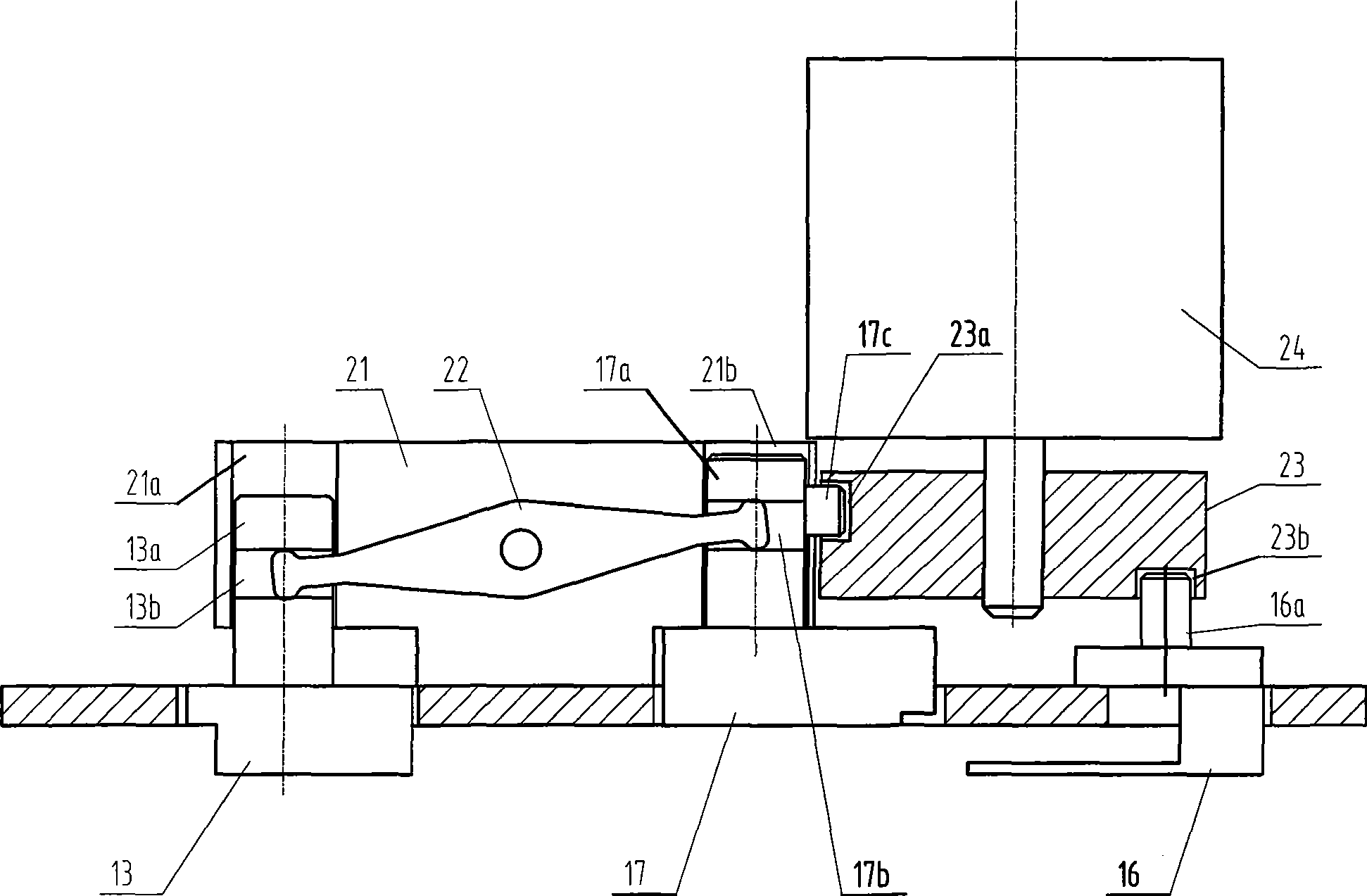

Image

  • Link gear of knitting cam
  • Link gear of knitting cam

Examples


Embodiment Construction

[0013] The present invention and its advantages will be further described below in conjunction with the drawings and embodiments.

[0014] This embodiment will use the three activities of the loop forming triangle (corresponding to the knitting triangle B), the transfer triangle (corresponding to the knitting triangle A) and the tuck triangle (corresponding to the knitting triangle C) in the computerized flat knitting machine. Weave a triangle to illustrate the invention.

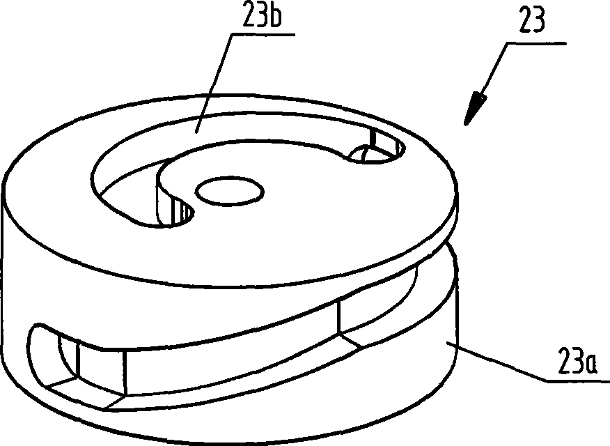
[0015] See figure 1 , The triangle linkage mechanism of the present invention is mainly composed of a mounting seat 21, a shift fork 22, a cam 23 and a motor 24. The shift fork 22 is hinged on the mounting base 21 and can rotate around the hinge point. Slot holes 21a and 21b are respectively provided on the mounting base 21 on both sides of the hinge point. The rear ends of the transfer cam 13 and the loop forming cam 17 are respectively provided with driving pins 13a, 17a, and the two driving pins are inserte...


PUM


Abstract

The invention relates to a knitting triangle link gear which includes an installation seat transmission fork and a knitting triangle, the transmission fork is hinged on the installing seat, two ends connect with a knitting triangle A and a knitting triangle B respectively, also includes a cam and a motor, a circle side and an end surface of the cam are equipped with a curved surface cam groove and a plane cam groove, the cam connects with an output shaft of the motor and locates on one side of the knitting triangle B, the knitting triangle B is inserted in the curved surface cam groove of the cam through a pin set on the knitting triangle B for driving joint, the knitting triangle C is inserted in the plane cam groove of the cam through a pin set on the knitting triangle C for driving joint, when the cam runs, the cam pushes corresponding knitting triangle moving through the curved surface cam groove and the plane cam groove respectively. The knitting triangle link gear has advantages that the knitting triangle link gear has fewer accessory, simple structure, low cost, succinct drive line and high reliability for moving which process link drive according with moving relationship among three knitting triangles.

Description

Technical field [0001] The invention relates to a computerized flat knitting machine, in particular to a knitting triangle linkage mechanism. Background technique [0002] Some cams in the knitting cam mechanism are movable and need corresponding drive mechanisms to drive them. In the existing knitting mechanism, these movable triangles are driven independently, and some are driven in linkage according to the mutual movement relationship. The linkage drive is generally limited to the drive of two movable triangles. Electromagnets and cams are often used to drive and control the movable knitting triangle, so that the linkage mechanism has many components, the structure is relatively complicated, and the manufacturing cost is not easy to reduce. Summary of the invention [0003] The purpose of the present invention is to propose a knitting cam linkage mechanism that can jointly drive three knitting cams and has a very simple structure, which is realized by the following technical ...

Claims


Application Information

Patent Timeline
Patent Type & Authority Applications(China)
IPC IPC(8): D04B15/36D04B15/96
Inventor 冯加林巫友群
Owner 冯加林
Learn More