Residual powder cleaning equipment

A technology for cleaning equipment and residual powder, which is applied to equipment, electrical recording technology, optics, etc. of the electrical recording process using charge graphics, and can solve the problems of low efficiency and high cost of residual powder cleaning

Inactive Publication Date: 2009-07-08
ZHUHAI SEINE TECH CO LTD
View PDF0 Cites 7 Cited by
  • Summary
  • Abstract
  • Description
  • Claims
  • Application Information

AI Technical Summary

Problems solved by technology

[0010] The invention provides a residual powder cleaning equipment to solve the existing technical problems of high cost and low efficiency of residual powder cleaning

Method used


Image

  • Residual powder cleaning equipment
  • Residual powder cleaning equipment
  • Residual powder cleaning equipment

Examples


Embodiment Construction

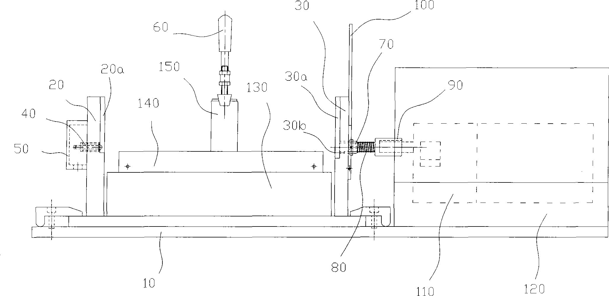
[0037] Such as image 3 As shown, a residual powder cleaning device is used to clean the toner on the toner box. The voltage supply section that supplies the voltage, the exposure section that exposes the photosensitive drum on the toner cartridge, the cleaning section that cleans the toner on the toner cartridge, and the toner cartridge support frame.

[0038] The powder box supporting frame includes a base 10 and a first side plate 20 and a second side plate 30 arranged at two ends of the base 10 matching the length of the powder box. The first side panel 20 and the second side panel 30 are installed on the base 10 and are perpendicular to the base 10 . The first side plate 20 and the second side plate 30 are respectively provided with grooves 20a, 30a, and the two ends of the powder box A are respectively supported by the grooves 20a, 30a on the first side plate 20 and the second side plate 30 , the distance between the grooves 20a, 30a on the first side plate 20 and the ...


PUM


Abstract

The invention relates to a residual powder cleaning device for a carbon powder box, which comprises a driving part which supplies power for the powder box, a voltage supply part which supplies voltage for the powder box, an exposure part which drives a light-sensing drum on the powder box to expose, a part for cleaning carbon powder on the cleaning powder box, and a powder box supporting frame. The residual powder cleaning device not only can effectively clean the carbon powder in a developing bin but also can not waste a printing medium, and simultaneously reduces the manufacturing cost; and the work efficiency of the residual powder cleaning device can not be influenced by the operating speed of an electrophotographic imaging device, so that the developing bin is quicker and more complete to clean. Moreover, the residual powder cleaning device solves the technical problems of high cleaning cost and low efficiency of the prior residual powder.

Description

technical field [0001] The invention relates to a powder box used on an electrophotographic imaging device (such as a laser printer, a copier, a fax machine), and in particular to a cleaning device for residual powder used on the powder box. Background technique [0002] Use a kind of powder box on the existing electrophotographic imaging device (as laser printer, photocopier, facsimile machine), the structure of this powder box is as follows: figure 1 shown. [0003] figure 1 Shown is an assembled toner cartridge A, including a developing part 1 and a photosensitive part 2. [0004] The developing part 1 comprises a powder bin 105, a developing bin 104 and a developing frame 107; the toner 108 can be stored on the powder bin 105; 104 and the powder bin 105 are separated by a seal 106, and the seal 106 can prevent the toner 108 from entering the developing bin 104 from the powder bin 105. [0005] The photosensitive part 2 includes a waste toner bin 206 , a photosensitiv...

Claims


Application Information

Patent Timeline
Patent Type & Authority Applications(China)
IPC IPC(8): G03G15/08G03G21/00
Inventor 李世云
Owner ZHUHAI SEINE TECH CO LTD
Why Eureka
Try Eureka