Wafer raising platform and wafer test machine

A wafer testing and lifting table technology, applied in semiconductor/solid-state device testing/measurement, electrical components, semiconductor/solid-state device manufacturing, etc.

Inactive Publication Date: 2009-07-08
KING YUAN ELECTRONICS
View PDF2 Cites 15 Cited by
  • Summary
  • Abstract
  • Description
  • Claims
  • Application Information

AI Technical Summary

Problems solved by technology

In addition, U.S. Patent No. 6,775,918 of the prior art discloses a wafer box with a positioning sensing device, which is characterized in that the positioning sensing device is a magnetic reed switch. , through the spring force of the magnetic reed switch to prevent the door of the crystal boat box from being closed accidentally, causing the wafer to break
However, when the transmission arm is in the process of grabbing the wafers in the wafer cassette, the above-mentioned previous proposal cannot solve the problem of whether the transmission arm is correctly positioned with the wafer in the wafer cassette to avoid fragmentation, or whether the transmission arm is in the Correct movement in the boat box to grasp the wafer, so how to solve the above problems has become an urgent issue in the industry

Method used


Image

  • Wafer raising platform and wafer test machine
  • Wafer raising platform and wafer test machine
  • Wafer raising platform and wafer test machine

Examples


Embodiment Construction

[0041] Since the present invention discloses a wafer lifting table and its wafer testing machine, the basic principle of wafer testing used therein has been understood by those with ordinary knowledge in the relevant technical field, so the following description will not be repeated. for a full description. At the same time, the diagrams compared below are structural representations related to the features of the present invention, and are not and need not be completely drawn according to the actual size, so please describe first.

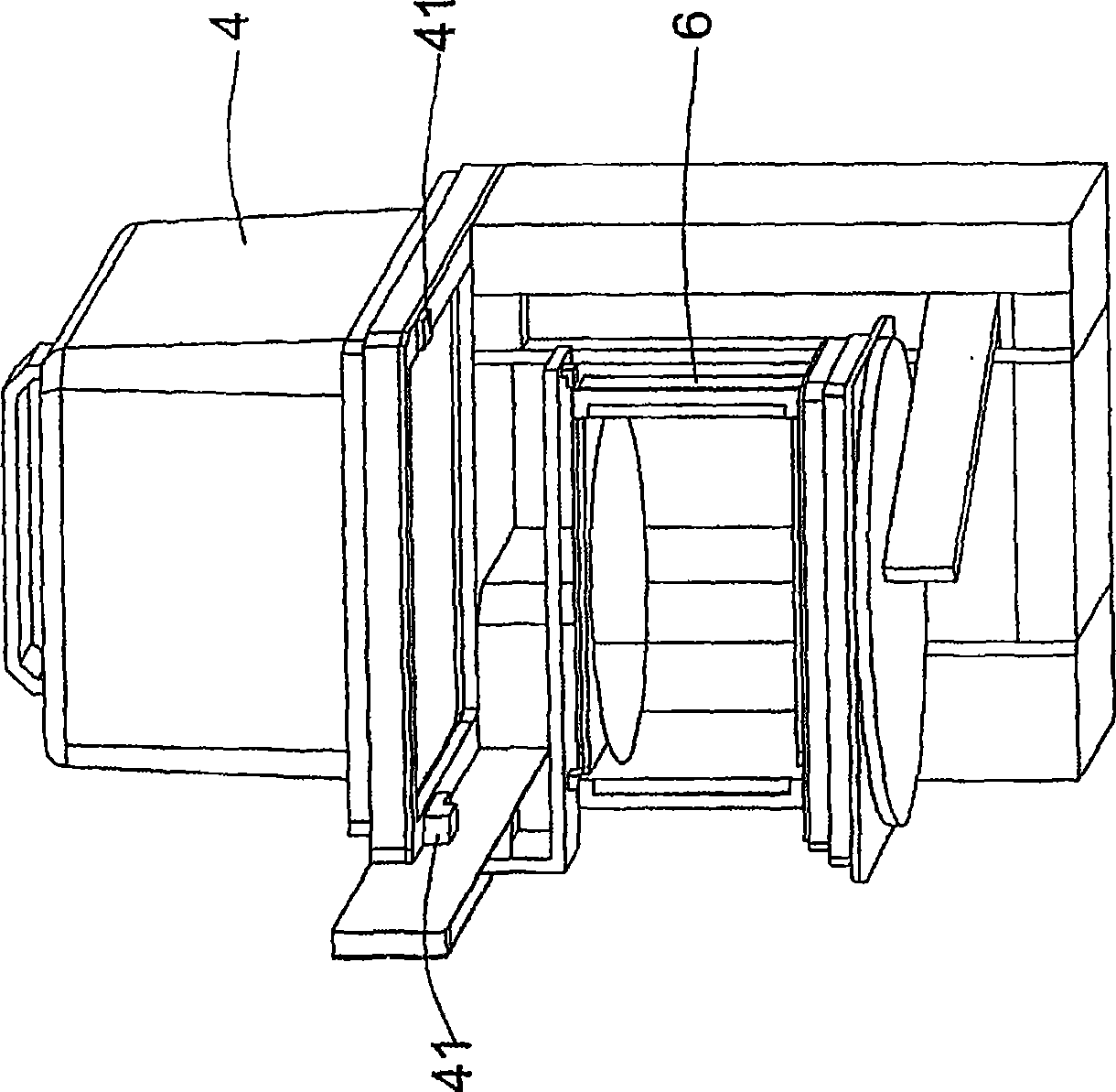
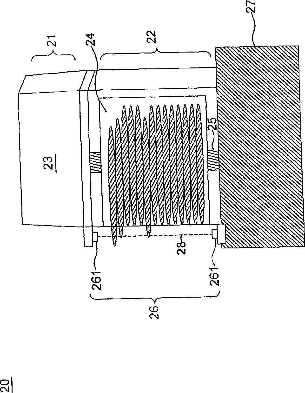
[0042] First please refer to figure 2 , is a schematic diagram of a wafer elevator according to the first preferred embodiment of the present invention. A wafer lifting platform 20 includes a first accommodating area 21 , a second accommodating area 22 , a driving module 25 (driving module), a sensing device 26 (sensing device), and a control device 27 .

[0043] The first accommodation area 21 accommodates at least one wafer box 23 (wafer POD),...


PUM


Abstract

The invention relates to a wafer lifting platform. The wafer lifting platform comprises a first containing zone and a second containing zone, a driver module, a sensing device and a control device, wherein, at least a wafer cassette is arranged in the first containing zone, and the wafer cassette comprises an opening to allow a boat for bearing a wafer to be moved to the second containing zone from the wafer cassette; the driver module is used for providing the position lifting for the boat; the control device is used for receiving signals sent by the sensing device and controlling the motion of the wafer lifting platform according to the signals; the wafer lifting platform is characterized in that the sensing area of the sensing device forms at least a datum plane in the second containing zone, the datum plane is close to the periphery of the wafer and is perpendicular to the plane of the wafer; and when the position of the wafer in the boat is shifted and the wafer forms influence with the datum plane to trigger the sensing device, the control device stops the operation of the wafer lifting platform.

Description

technical field [0001] The invention relates to a wafer lifting table and its testing machine, in particular to a wafer lifting table with a sensing device and its testing machine. Background technique [0002] At present, before wafer testing, the operator will place the wafer boat (cassette) containing the wafer in the wafer box (pod) of the wafer lifting table, and then the wafer will be lowered by the wafer lifting table Transfer to a location accessible by the transfer arm for subsequent wafer testing. However, when the wafer boat is conveyed by the wafer lifting platform, the wafers in the wafer boat may be out of position more or less due to the movement of the wafer boat. In prior art U.S. Patent No. 5,601,484 has disclosed a wafer transfer device with a sensing device, such as figure 1 As shown, it is characterized in that the sensing device 41 is horizontally installed on the two parts of the accommodation plate below the wafer cassette 4. When the wafer cassette...

Claims


Application Information

Patent Timeline
Patent Type & Authority Applications(China)
IPC IPC(8): H01L21/683H01L21/66
Inventor 林世芳李沛勋
Owner KING YUAN ELECTRONICS
Why Eureka
Try Eureka