Stator for rotary electric machine, and rotary electric machine using the stator
A technology for a rotating electrical machine and a stator is applied in the field of a stator for a rotating electrical machine and a rotating electrical machine using the stator, which can solve problems such as increasing the size of the stator, and achieve the effects of size reduction, cost reduction, and suppression of performance degradation.
Active Publication Date: 2009-07-08
DENSO CORP
View PDF1 Cites 19 Cited by
- Summary
- Abstract
- Description
- Claims
- Application Information
AI Technical Summary
Problems solved by technology
Therefore, when these unit wire ends are connected, additional space is required in the axial dire
Method used
View moreImage
Smart ImageViewing Examples

Examples
 PUM
 Abstract
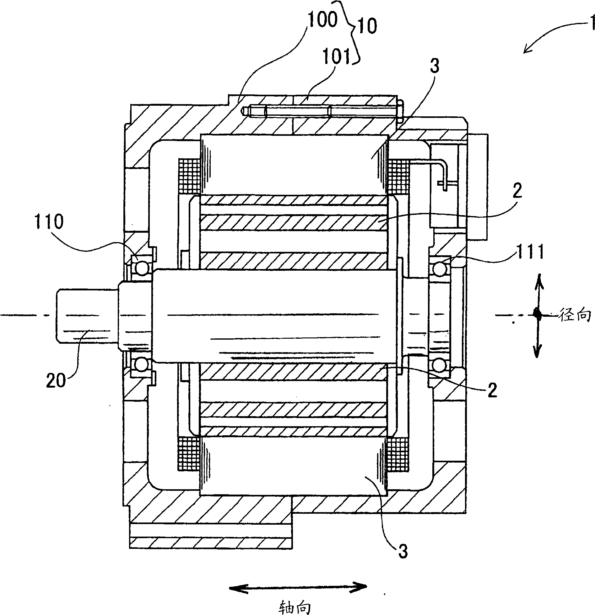
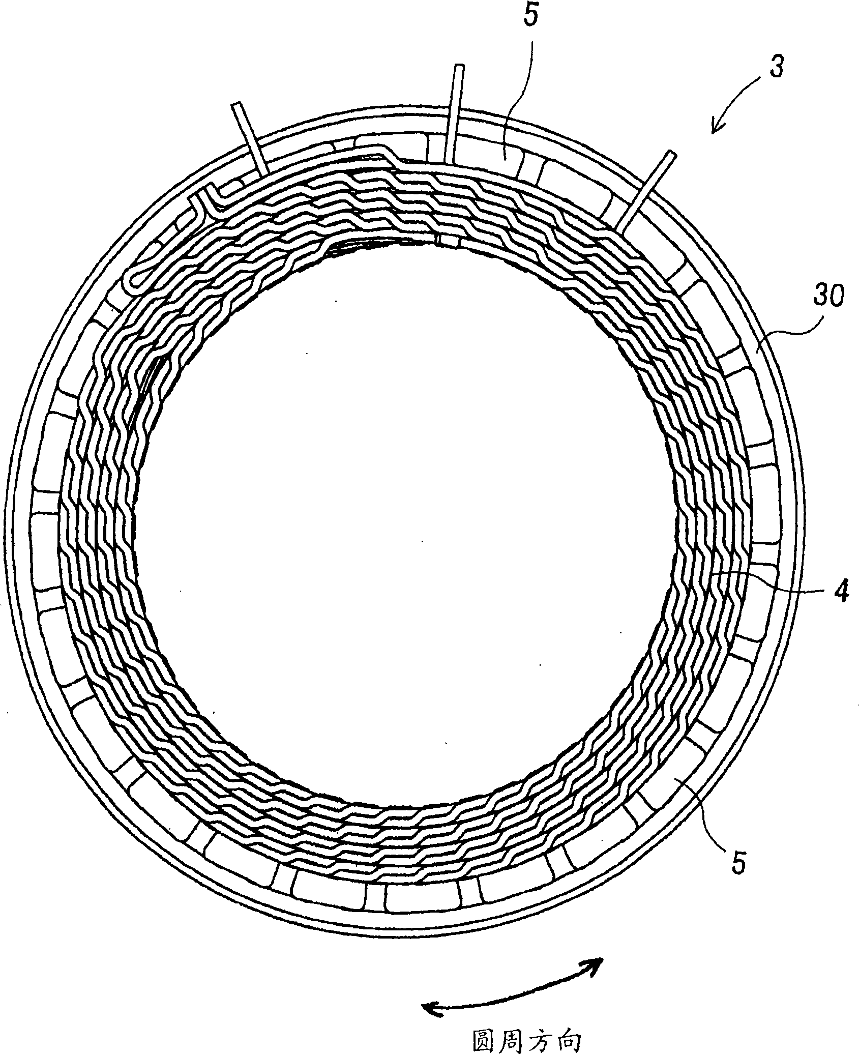
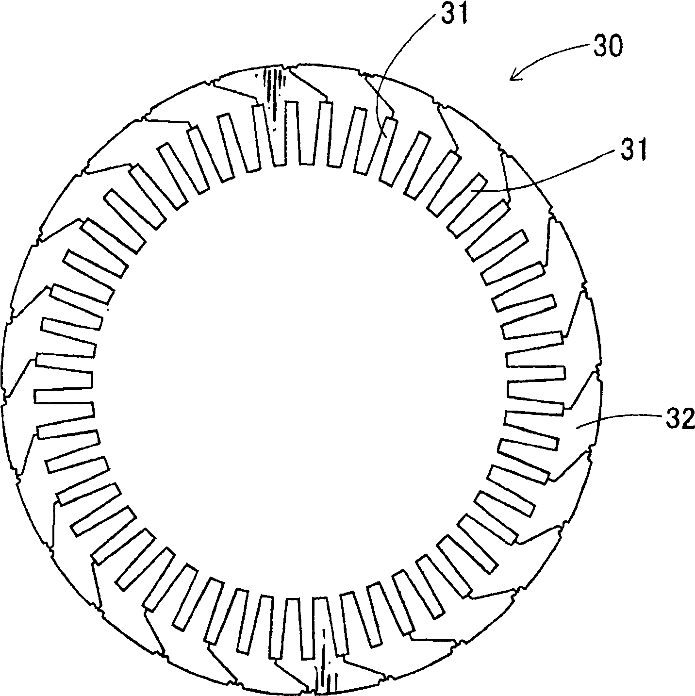
A stator for a multiple-phase rotary electric machine provided a stator core with slots and a coil formed of a plurality of windings for individual phases. Each winding has slot-accommodated portions held in different slots, turn portions connecting the slot-accommodated portions outside of the slots in an axial direction, and a return portion that connects two of the turn portions and changes a winding direction of the winding at given slots. The turn portions include specific turn portions which are the same in a circumferential position as the turn portion connected to the one of the return portion. The specific turn portions are located, in a radial direction, to be drawn apart from the rotor than the slot-accommodated portions connected to the specific turn portions.
Description
technical field [0001] The present invention relates to a stator for a rotary electric machine, and a rotary electric machine using the same. Background technique [0002] Recently, there is a need to use a miniaturized and high-power rotating electric machine as a motor or a generator. [0003] For example, in the case of a rotating electrical machine mounted on a vehicle, the space for loading such a rotating electrical machine is becoming smaller, but its output is required to be higher. [0004] Various types of rotating electrical machines have been used. For example, some such conventional rotating electric machines are disclosed in Japanese Patent Laid-Open Nos. 2002-176752 and 2004-320886. [0005] Each of these references discloses a stator for a rotating electrical machine. The stator for a rotating electric machine disclosed in each of these documents has a coil formed by continuous winding. [0006] In the rotating electric machines described in these referen...
Claims
Login to View More Application Information
Patent Timeline
 IPC IPC(8): H02K1/12H02K3/04H02K3/28H02K15/085
Inventor 小川新一香田请司七条彰哉前川武雄
Owner DENSO CORP
Features
- R&D
- Intellectual Property
- Life Sciences
- Materials
- Tech Scout
- Unparalleled Data Quality
- Higher Quality Content
- 60% Fewer Hallucinations
Learn More Browse by: Latest US Patents, China's latest patents, Technical Efficacy Thesaurus, Application Domain, Technology Topic, Popular Technical Reports.
© 2025 PatSnap. All rights reserved.Legal|Privacy policy|Modern Slavery Act Transparency Statement|Sitemap|About US| Contact US: help@patsnap.com