Eureka AIR delivers breakthrough ideas for toughest innovation challenges, trusted by R&D personnel around the world.

Micro motor

A micro-motor and micro-technology, applied in the direction of electrical components, electromechanical devices, electric components, etc., can solve the problems of increasing friction loss of rotor components, left-right deviation, and reducing motor efficiency, etc., and achieve low assembly requirements and ensure axial concentricity degree of effect

Inactive Publication Date: 2009-07-08
徐黎霞
View PDF0 Cites 2 Cited by
  • Summary
  • Abstract
  • Description
  • Claims
  • Application Information

AI Technical Summary

Problems solved by technology

[0003] Electromagnetic micro motors generally include a stator assembly and a rotor assembly. The rotor assembly includes a shaft and a permanent magnet rotor that can rotate with the shaft. The stator assembly generally includes front claw poles, front bushings, rear claw poles, and rear bushings. , the stator frame and the stator coil wound on the stator frame, the permanent magnet rotor and the rotating shaft are generally two separate parts, the permanent magnet rotor is generally hooped on the rotating shaft, and the two ends of the rotating shaft pass through the front claw pole, the front bushing, the rear Claw poles, rear bushings, and permanent magnet rotors are prone to deflection when rotating, so it is difficult to ensure the axial concentricity between the entire rotor assembly and the stator assembly, and the gap between the rotor assembly and the stator assembly uneven, and the deviation of the permanent magnet rotor will increase the friction loss of the rotor assembly itself, reducing the efficiency of the entire motor
[0004] In addition, many micro motors are used in places with water, such as micro water current generators. In this way, the stator assembly and rotor assembly of the micro motor need to be covered with a waterproof and sealed casing. For the convenience of processing and installation, the rotor assembly and stator assembly are generally After being assembled in the casing, the cover is pressed and sealed. When this waterproof micro motor is assembled, the seal - the cover is installed, and the cover generally presses the rotor assembly and the stator assembly in the stator frame, so that It is easy to cause the rotor assembly to be unevenly stressed and deviate left and right. At this time, it is more difficult to ensure the axial concentricity between the rotor assembly and the stator assembly.

Method used


Image

  • Micro motor
  • Micro motor
  • Micro motor

Examples


Embodiment Construction

[0019] The present invention will be further described in detail below in conjunction with the accompanying drawings and embodiments.

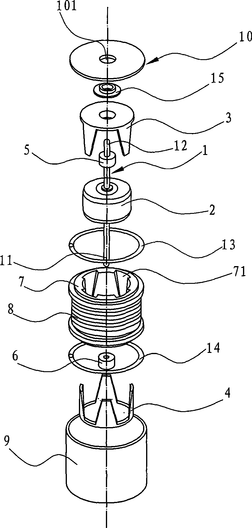
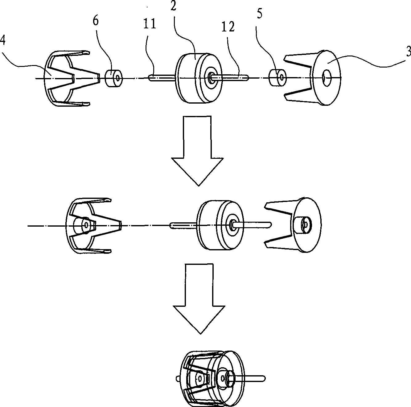
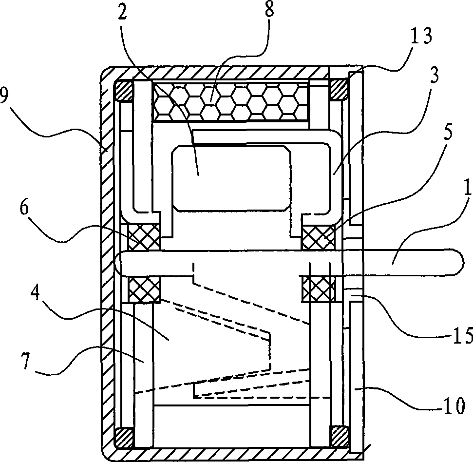
[0020] Such as Figure 1~3 The micro motor shown includes a rotor assembly formed by a stainless steel shaft 1 and a ferrite permanent magnet rotor 2 through a mold positioning injection molding process. , a stator assembly composed of a hollow tubular stator frame 7 and a stator coil 8 wound on the outer surface of the stator frame, wherein the front claw pole 3 and the rear claw pole 4 are stainless steel toothed claw poles, which are also formed by stamping at one time, and the front claw poles and the center hole of the rear claw pole are turned inward to form a bushing hole, the front bushing 5 is directly embedded in the center hole 31 of the front claw pole 3, and the rear bushing 6 is directly embedded in the center hole 41 of the rear claw pole 4, Then the rear end 11 of the rotating shaft 1 formed once with the permanent magnet roto...


PUM


Abstract

The invention relates to a micro-motor which comprises a stator module and a rotor module installed in the stator module. The stator module comprises a hollow stator framework, a coil wound outside the stator framework, and a front claw pole and a back claw pole located in the stator framework; the rotor module comprises a rotating shaft and a permanent magnet rotor which can rotate with the rotating shaft and is located in the chamber of the stator framework; the micro-motor is characterized in that a front shaft sleeve and a back shaft sleeve are fixedly embedded in the centers of the front and the back claw poles respectively, and the two ends of the rotating shaft of the rotor module can be rotatablely supported in the front and the back shaft sleeves respectively. Compared with the prior art, the micro-motor has the advantages that the front and the back shaft sleeves are directly embedded in the central holes of the front and back poles respectively, the two ends of the rotating shaft rotate under rigid support of the front and the back shaft sleeves, thereby better ensuring axial coaxiality of the rotor module and the stator module and even clearance between the rotor module and the stator module when the permanent magnet rotates.

Description

technical field [0001] The invention relates to a micromotor, in particular to a claw-pole micromotor. Background technique [0002] Motor is the general term for electric motor and generator, which is used to complete the energy conversion between mechanical energy and electrical energy. The micro motor is a main branch of the motor, which can be roughly divided into three categories in structure: ① electromagnetic type, the basic composition is similar to that of ordinary motors, including stator components, rotor components, armature windings, brushes and other components; ② combined type, There are two common types: the combination of the above-mentioned micro-motors, the combination of micro-motors and electronic circuits, such as the combination of DC motors and sensors, the combination of X-direction and Y-direction linear motors, etc.; ③ non-electromagnetic type. The electromagnetic micro motor is the most common one, and among the electromagnetic micro motors, the ...

Claims


Application Information

Patent Timeline
Patent Type & Authority Applications(China)
IPC IPC(8): H02K21/12H02K5/10H02K5/16
Inventor 颜志洪
Owner 徐黎霞
Why Eureka
Eureka Blog
Learn More