Pulse controlling and state monitoring device for H bridge cascade high voltage transformer power unit

A high-voltage inverter and power unit technology, applied in the field of high-voltage inverters, can solve the problems of complex functions of the pulse distribution part of the main controller, complex control circuits, and high failure rates, and achieve the goals of reducing the number of optical fibers, simple implementation methods, and simplified circuits. Effect

Inactive Publication Date: 2009-07-08
ANHUI E S ELECTRIC TECH
View PDF0 Cites 21 Cited by
  • Summary
  • Abstract
  • Description
  • Claims
  • Application Information

AI Technical Summary

Problems solved by technology

Both of the above two processing methods are applied, it is not difficult to see that figure 2 The method shown in although the communication fiber between each power unit and the main controller is figure 1 In the middle method, 4 are reduced to 2, but the pulse distribution function of the main controller is still very complicated, and there are still many optical fibers (30-60), not only the control circuit is complicated, but also the failure rate is high

Method used


Image

  • Pulse controlling and state monitoring device for H bridge cascade high voltage transformer power unit
  • Pulse controlling and state monitoring device for H bridge cascade high voltage transformer power unit
  • Pulse controlling and state monitoring device for H bridge cascade high voltage transformer power unit

Examples


Embodiment Construction

[0021] The technical solution of the present invention will be described in further detail below according to the accompanying drawings.

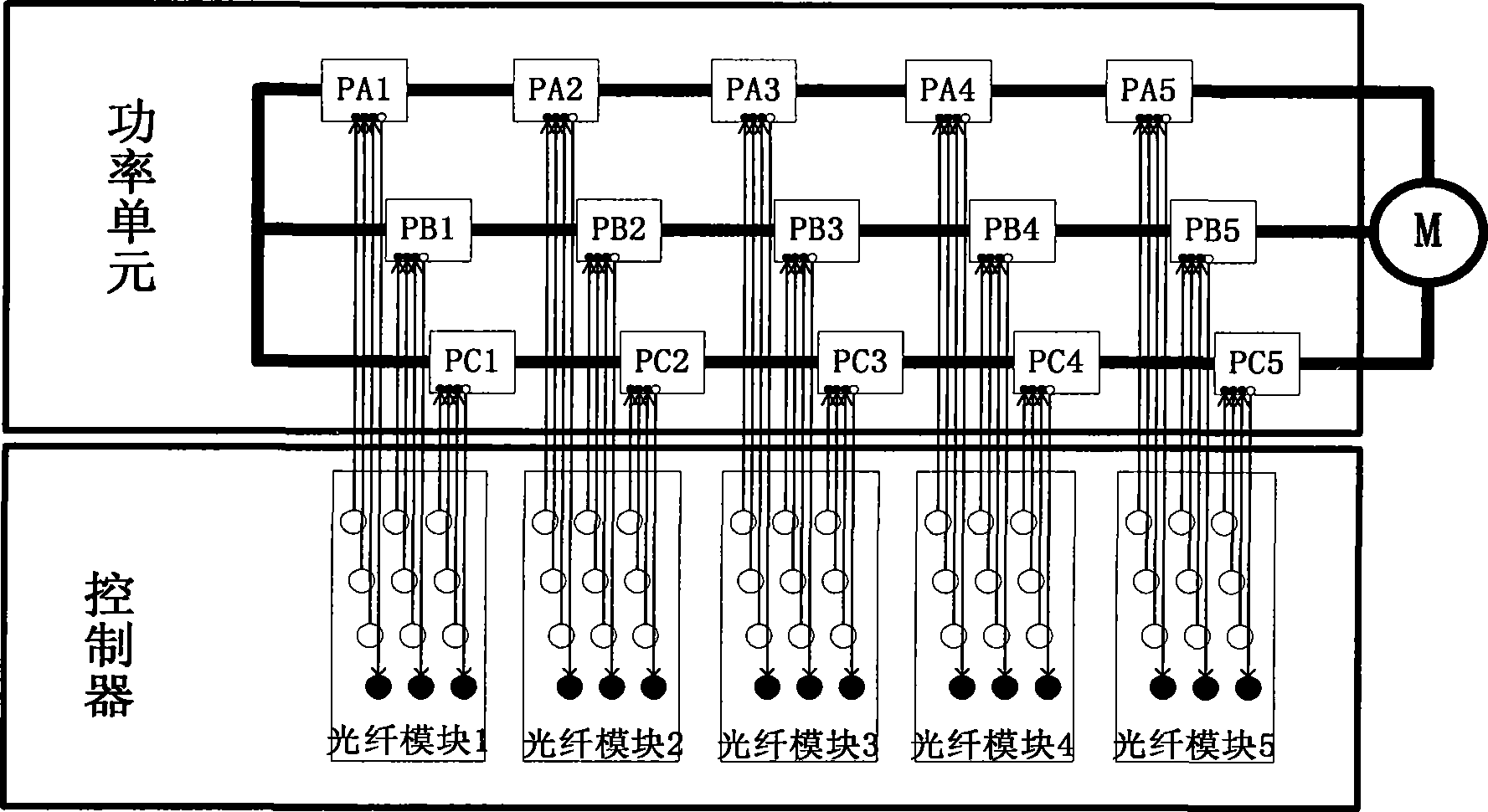
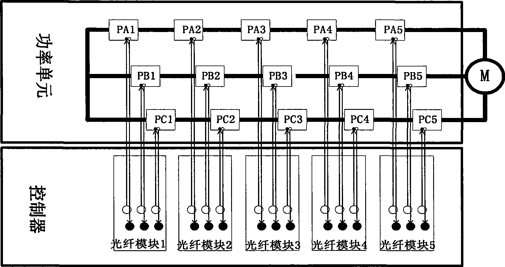
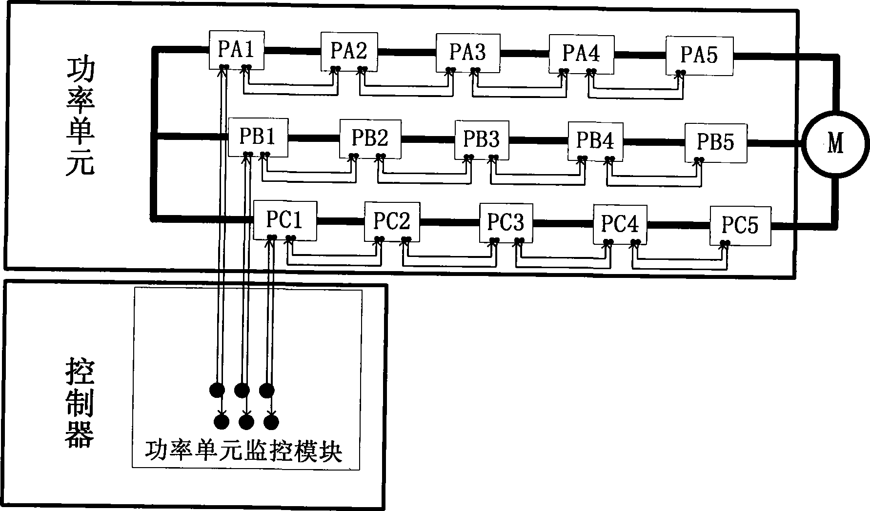
[0022] Such as image 3 As shown, the H-bridge cascaded high-voltage inverter power unit pulse control and state monitoring device disclosed in the present invention includes a controller part and a control circuit part in each power unit. H-bridge cascaded high-voltage inverter is a three-phase inverter used to control motors. Each phase of the inverter is composed of the same number of multi-stage H-bridge power units PA1-PA5, PB1-PB5, and PC1-PC5 connected in series. From image 3 It can be seen from the figure that the controller and the power unit are connected through two optical fibers, one of which is used for the controller to send transmission pulses and For control signals, the other optical fiber is used to transmit status signals of all power units PA1-PA5, PB1-PB5, and PC1-PC5 of the phase back to the controller.

[0023] I...


PUM


Abstract

The invention discloses a novel device for impulse control and status monitoring of a power unit on an H-bridge concatenated high-pressure frequency changer. In the device that is designed for the H-bridge concatenated high-pressure frequency changer, pulses and command data in each phase of the high-pressure frequency changer are sent down to a first power unit Px1 (x denotes an A phase, a B phase and a C phase, same as below) of the phase by command fibers in a controller, and pulse data and command data are processed through analysis and phase-shifting by the Px1 and then are transmitted down sequentially; status data is sent to a previous power unit by status fibers from the last power unit (such as Px5) of the phase, is uploaded sequentially after being packed, and is uploaded to a fiber data transceiver module finally; and so the complete series connection of the fibers can be realized, and the number of fibers and the structure of a control circuit can be reduced greatly.

Description

technical field [0001] The invention belongs to the technical field of high-voltage frequency converters, relates to industrial optical fiber communication technology, and in particular provides a pulse control and power unit state monitoring device for H-bridge cascaded high-voltage frequency converter power units. The device is aimed at H-bridge cascaded Designed with a high-voltage frequency converter, it can complete the pulse distribution of all power units, the control function and the status monitoring of each power unit through two optical fibers per phase. Background technique [0002] With the increasingly tense energy situation and the intensification of environmental deterioration, energy conservation and emission reduction have become the consensus of all countries in the world, and China, which is the largest energy-consuming country in developing countries, has become more serious about this problem. According to authoritative statistics, 70-80% of domestic el...

Claims


Application Information

Patent Timeline
Patent Type & Authority Applications(China)
IPC IPC(8): H02M5/00
CPCH02M7/49H02M1/0003
Inventor 洪婷婷夏稳
Owner ANHUI E S ELECTRIC TECH
Why Eureka
Try Eureka