

Downlink control information sending and detecting method
A technology of control information and transmission method, which is applied in the directions of access restriction, wireless communication, electrical components, etc., and can solve the problem that the form of downlink control information does not have a corresponding description.
- Summary
- Abstract
- Description
- Claims
- Application Information
AI Technical Summary
Problems solved by technology
Method used
Image

Examples
Embodiment 1
[0101] Sending process of downlink control information
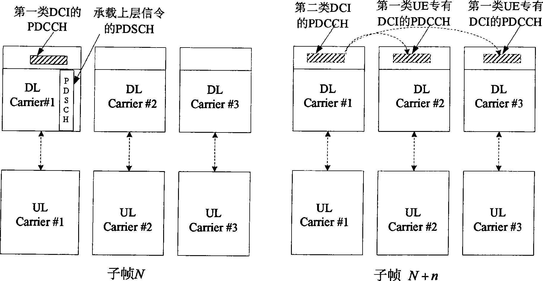
[0102] As shown in Figure 2(a). The LTE-Advanced terminal is initially allocated only the downlink component carrier DLCarrier#1. The high layer signaling carried by the PDSCH is received in subframe N. The high layer signaling indicates that the terminal detects PDCCH on the downlink component carriers DL Carrier#1, DL Carrier#2 and DL Carrier#3, and the second type of DCI is on the DL Carrier#1. The high-level signaling may also include the frequency position of each component carrier, the system bandwidth of each component carrier, the transmission mode of each component carrier, the start / stop of PDCCH detection (reception) of each component carrier, and the One or more types of information such as the detected (received) time length, and the detected (received) time period of each component carrier.
[0103] The terminal starts to perform PDCCH blind detection of the first-type DCI and the second-type DCI at subf...
Embodiment 2
[0111] Type 1 DCI and Type 2 DCI
[0112] The indication information related to the first type of terminal-specific DCI included in the second type of DCI may include one or more of the following information:
[0113] Indicates whether there is UE-specific DCI in the component carrier
[0114] A component carrier is represented by 1 bit. For example, 0 indicates that there is no UE-specific DCI in the component carrier; 1 indicates that the component carrier has UE-specific DCI.
[0115] Indicates the DCI format
[0116] A component carrier is represented by 2 bits. For example, 00 indicates that there is no UE-specific DCI in the component carrier; 01 indicates that there is one DCI format in the component carrier; 10 indicates that there is another DCI format in the component carrier; 11 indicates that there are two DCI formats in the component carrier.
[0117] Indicate DCI format and CCE aggregation level
[0118] A terminal-specific DCI format on a component ca...
Embodiment 3
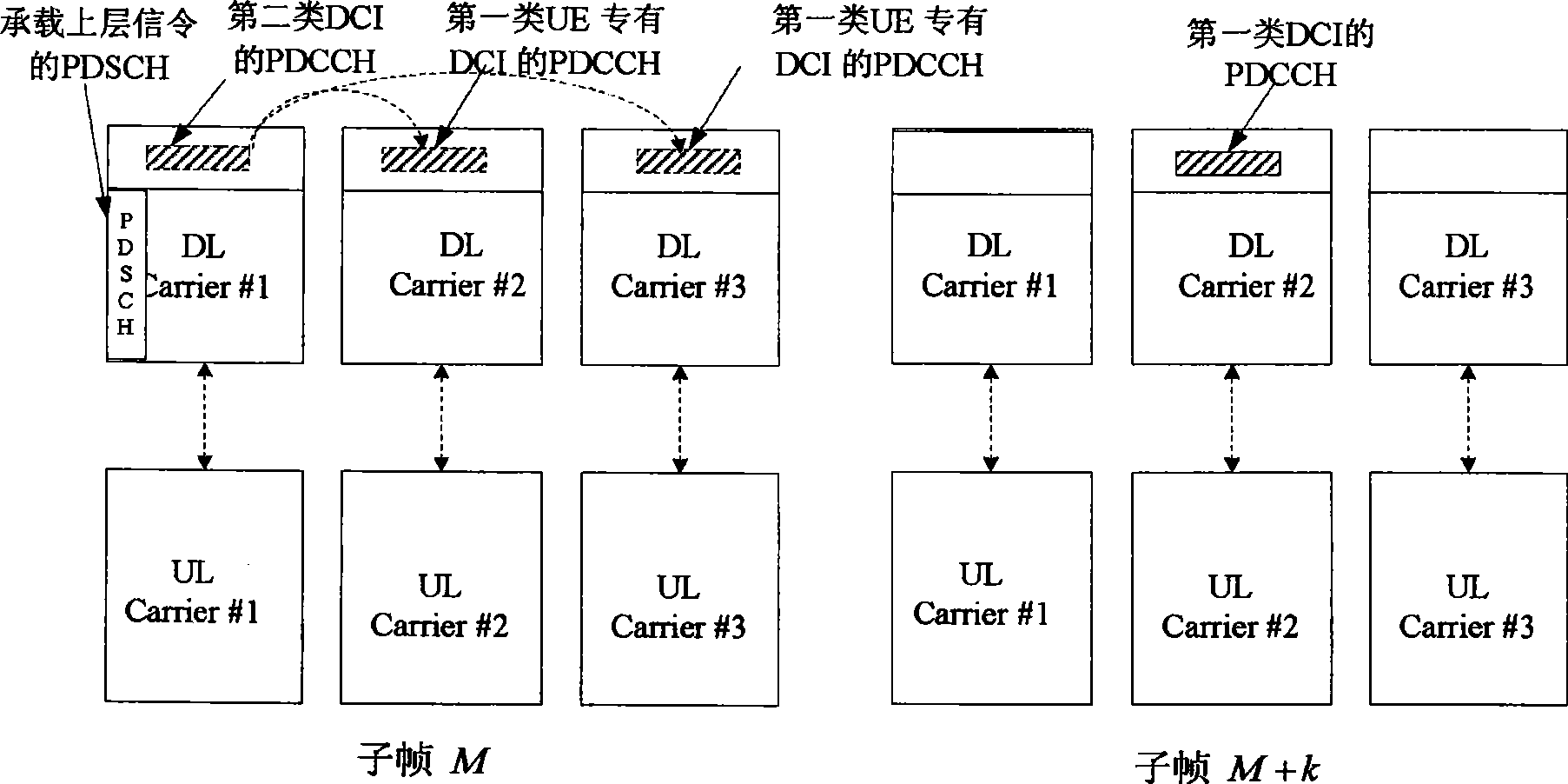
[0125] Detection methods of type 1 DCI and type 2 DCI
[0126] Such as image 3 As shown, the two types of DCI correspond to the decoding PDCCH blind detection DCI method on the component carrier as follows:
[0127] 1) On component carrier DL Carrier#1, first blindly detect the second type of DCI, and then blindly detect the first type of DCI;
[0128] 2) On component carrier DL Carrier#2 and component carrier DL Carrier#3, first blindly detect the first type of public DCI, and then blindly detect the first type of terminal-specific DCI;
[0129] The PDCCH carrying the second type of DCI is in the terminal-specific search space, or in the public and terminal-specific search spaces.
[0130] When the second type of DCI is detected by decoding the PDCCH on the component carrier DL Carrier#1, and the indication information in it is consistent with the existing results of decoding the PDCCH blind detection of the first type of DCI on the component carrier DL Carrier#2 and compone...
PUM
 Abstract
Description
Claims
Application Information