

Modular storage system for laboratory fluids
A storage system and laboratory technology, applied in the field of modular storage system, can solve the problem of expensive reagents
- Summary
- Abstract
- Description
- Claims
- Application Information
AI Technical Summary
Problems solved by technology
Method used
Image

Examples
Embodiment Construction
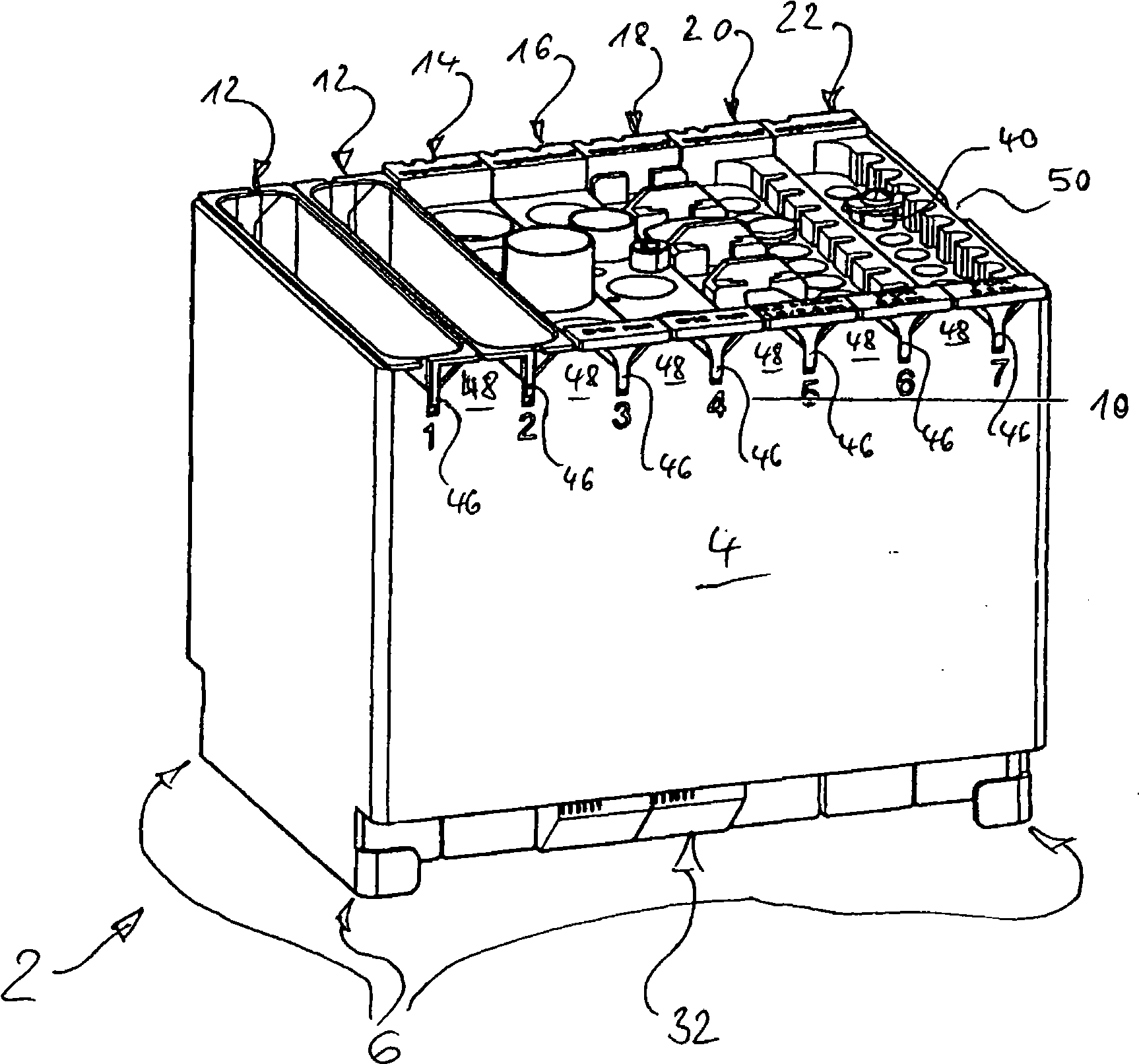
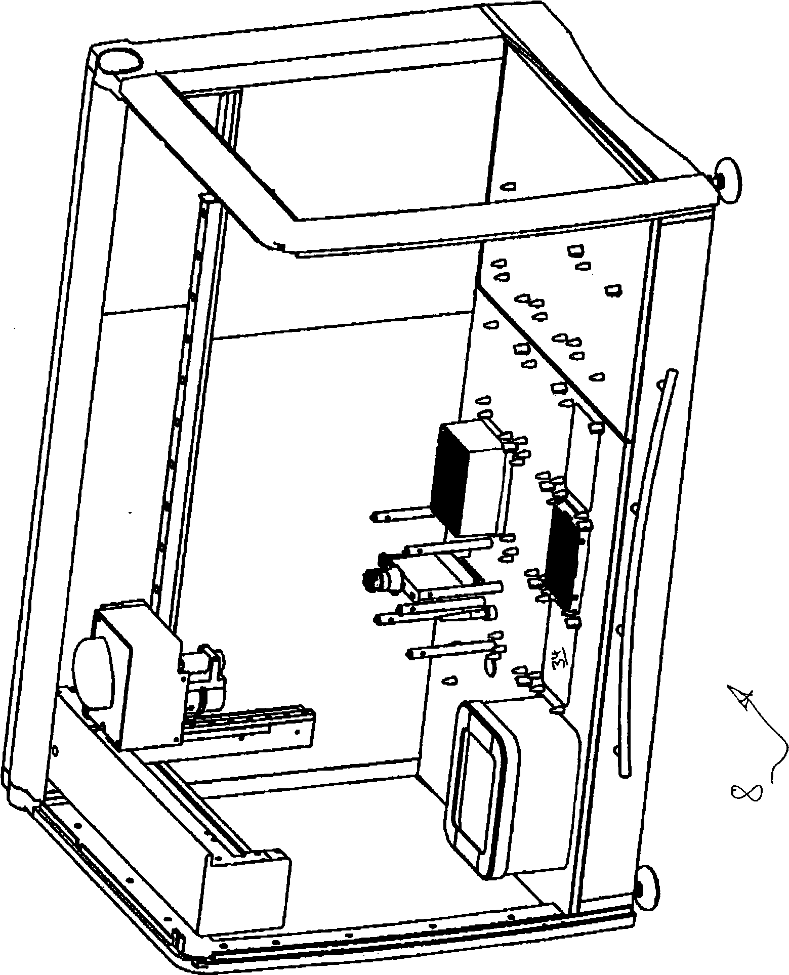
[0041] Figure 1 shows a modular storage system 2 for laboratory liquids (not shown) with brackets 4 formed by bending sheet metal. The carrier 4 has a microplate (6) in SBS standard form on the bottom side. Thus, the bracket 4 can be inserted in an interlocking manner in different positions such as in the workstation 8 ( FIG. 3 ), or in other laboratory devices provided for such connection measures.
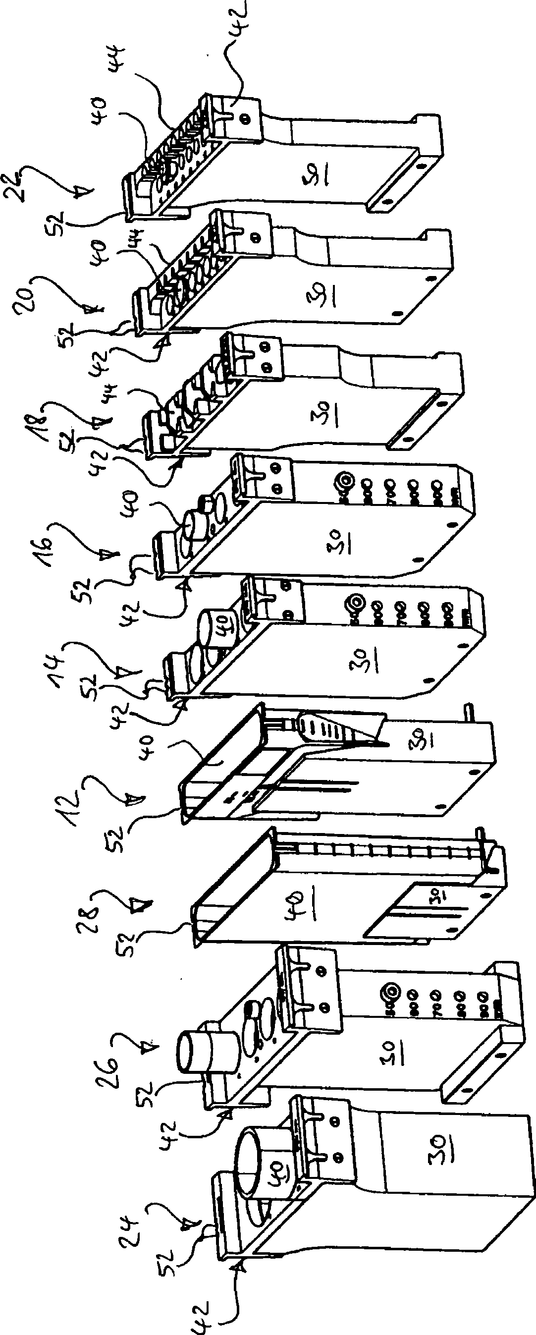
[0042] Still according to the carrier 4 of FIG. 1 , there are a total of seven slots 10 for the labware inserts 12 to 22 . In each case, the slots 10 numbered 1 and 2 are equipped with identical labware inserts 12 in the form of lower slots (see FIG. 2 ), while the remaining slots 10 numbered 3 to 7 are in each The cases are provided with labware inserts for at least four labware in each case.
[0043] For transport purposes in the workstation 8, the racks 4 and the respective labware inserts 12 to 28 have gripping structures so that the racks with these inserted labware insert...
PUM
 Abstract
Description
Claims
Application Information