Centrifugal subsidence mixed dirt remover

A centrifugal sedimentation and mixing technology, which is applied in the direction of the swirling device and the swirling device in which the axial direction of the swirl can be reversed, can solve the problems of difficult removal of impurities, low decontamination efficiency of the decontamination device, etc. Effect

Inactive Publication Date: 2009-07-15
HARBIN INST OF TECH
View PDF1 Cites 22 Cited by
  • Summary
  • Abstract
  • Description
  • Claims
  • Application Information

AI Technical Summary

Problems solved by technology

[0003] The purpose of the present invention is to provide a centrifugal sedimentation hybrid decontamination device to solve the problems of low decontamination efficiency of existing decontamination devices and difficulty in removing impurities with small particles

Method used


Image

  • Centrifugal subsidence mixed dirt remover
  • Centrifugal subsidence mixed dirt remover

Examples


specific Embodiment approach

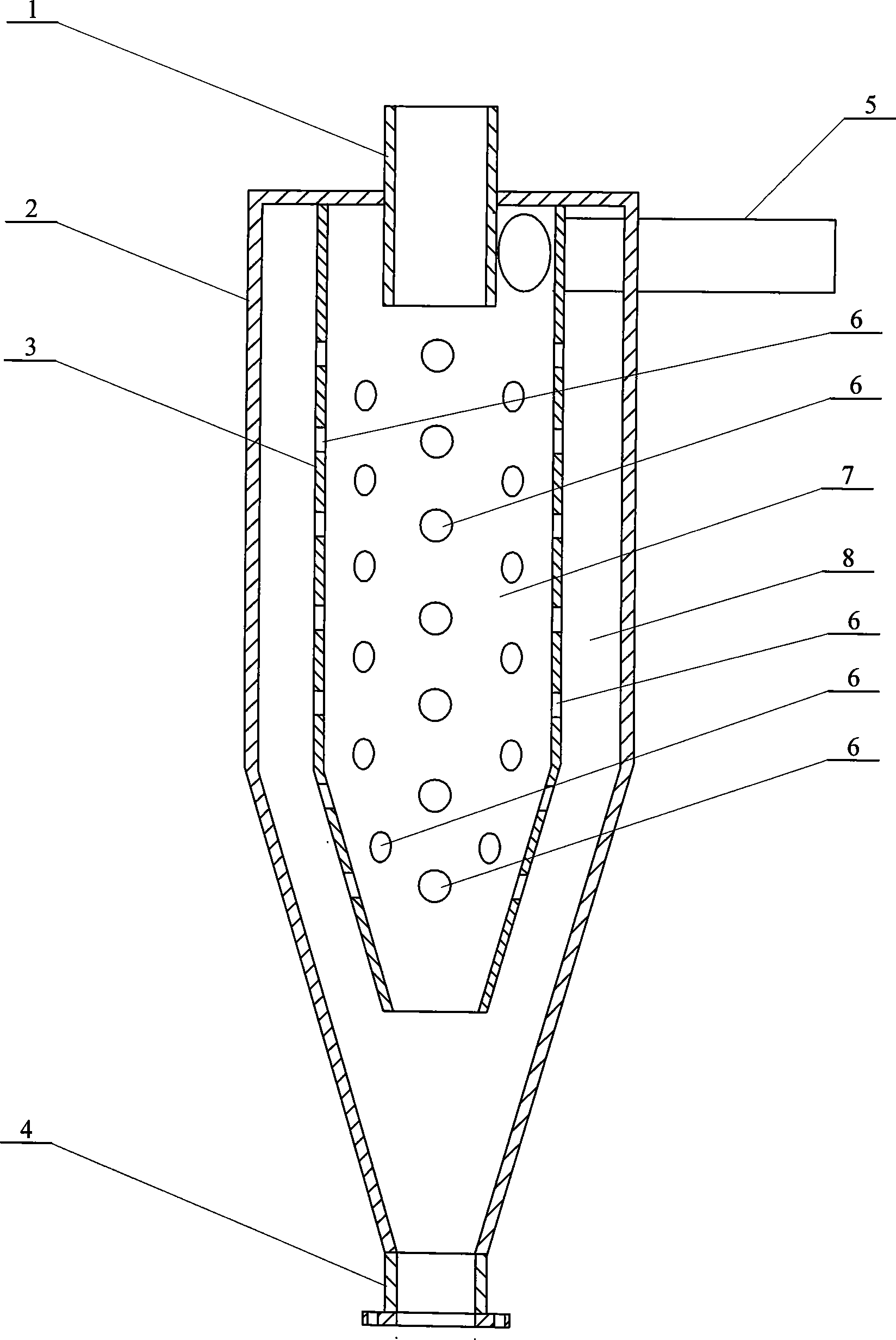
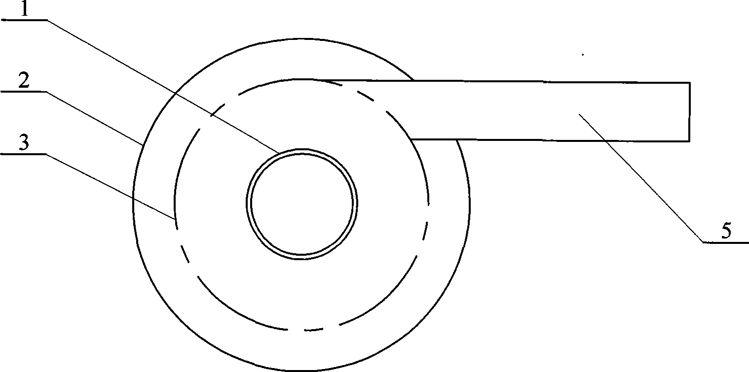
[0006] Specific implementation methods: (see figure 1 and figure 2 ) This embodiment consists of a water outlet pipe 1, an outer cylinder 2, an inner cylinder 3, a dirt discharge pipe 4 and a water inlet pipe 5. The dirt discharge pipe 4 communicates with the lower end of the outer cylinder 2. The top is connected, the inner cylinder 3 is set in the outer cylinder 2, the inner cylinder 3 is coaxial with the outer cylinder 2, the upper end of the inner cylinder 3 is fixedly connected with the inner wall of the top cover of the outer cylinder 2, and a through hole is opened on the wall of the inner cylinder 3 6. The inner space of the inner cylinder 3 is the swirl zone 7, the space between the inner cylinder 3 and the outer cylinder 2 is the settlement zone 8, one end of the water inlet pipe 5 is connected to the upper side wall of the inner cylinder 3, and the water inlet pipe 5 is cut It enters the inner cylinder 3 and communicates with the swirl zone 7 inside the inner cyli...


PUM


Abstract

The invention relates to a dirt separator, in particular to a centrifugal sedimentation composite type dirt separator, which aims at solving the problems of low dirt removing efficiency and difficult granular impurities removing of the prior dirt separator. The dirt separator adopts the structure that an inner cylinder is arranged in an outer cylinder and is coaxial with the outer cylinder, and the upper end of the inner cylinder is fixedly connected with the inner wall of a top cover of the outer cylinder; the wall of the inner cylinder is provided with a through hole, the inner space of the inner cylinder is a rotational flow region, the space between the inner cylinder and the outer cylinder is a sedimentation region, and one end of a water feeding pipe is connected to the lateral wall of the upper end of the inner cylinder and communicated with the rotational flow region inside the inner cylinder. The invention separates a whole flow field into the rotational flow region inside the inner cylinder and the sedimentation region positioned between the inner cylinder and the outer cylinder, a fluid entering the inner part of the dirt separator is rotationally separated and then enters the sedimentation region through the through hole positioned on the wall of the inner cylinder from the rotational flow region, and solid impurities with small grain diameters ranging from 0.075 mm to 1 mm enter the sedimentation region and are separated by low-speed sedimentation.

Description

technical field [0001] The invention relates to a decontamination device. Background technique [0002] The impurities in the water of the heating pipe network are mainly the molding sand used in the casting process of the radiator in the cast iron radiator. The molding sand of the cast iron radiator falls off and enters the pipe network during the operation of the pipe network. Since it is not effectively removed in the decontamination device, it is brought into the In the boiler and deposited on the tube wall of the boiler, it will cause uneven heating of the boiler and even cause the boiler tube to burst. Therefore, removing impurities in the pipe network is very necessary for the safe and economical operation of the boiler. In order to solve the above problems, the Chinese patent application number is 90221371.7, the announcement number is CN2096419U, the announcement date is February 19, 1992, and the utility model patent application named "cyclone decontamination devic...

Claims


Application Information

Patent Timeline
Patent Type & Authority Applications(China)
IPC IPC(8): B04C5/10B04C5/081B04C5/04
Inventor 赵华
Owner HARBIN INST OF TECH
Why Eureka
Try Eureka