Splicing machining method for ion beam machining optical element

A technology of an optical element and a processing method, which is applied in the field of sub-regional splicing and processing of ion beam processing optical elements, can solve the problems of increased maintenance cost and the like

Inactive Publication Date: 2009-07-15
NAT UNIV OF DEFENSE TECH
View PDF0 Cites 11 Cited by
  • Summary
  • Abstract
  • Description
  • Claims
  • Application Information

AI Technical Summary

Problems solved by technology

However, the principle of material removal in ion beam processing determines that the entire processing process must be completed in a vacuum environment. As a result, the processing system increases with the increase in the size of the mirror, and the cost of construction, use and maintenance also increases. How to innovate the processing method To tap the processing capacity of existing small equipment, it is still blank at home and abroad

Method used


Image

  • Splicing machining method for ion beam machining optical element
  • Splicing machining method for ion beam machining optical element
  • Splicing machining method for ion beam machining optical element

Examples


Embodiment

[0048] The ion beam polishing modification process of the present embodiment is carried out on an ion beam polishing equipment (KDIFS-500 type can be selected), and the modification process parameters are set to: the working gas is argon, and the working vacuum is 0.8×10 -2 Pa, ion energy 1100eV, beam current 25mA.

[0049] The optical element to be polished is ordinary glass-ceramics with a diameter of 84mm.

[0050] Carry out ion beam polishing to above-mentioned glass ceramics by following method step:

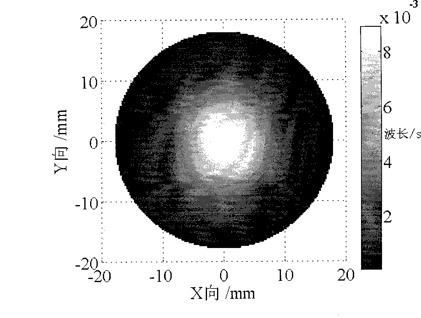
[0051] 1. Determine the removal function: apply the above-mentioned ion beam modification process to carry out the removal function experiment, and the obtained removal function is denoted as R(x, y), and its distribution is as follows figure 1 As shown, the diameter d=36mm of the removal function; the removal function is discretized with an interval S, and expressed as a matrix is ​​R;

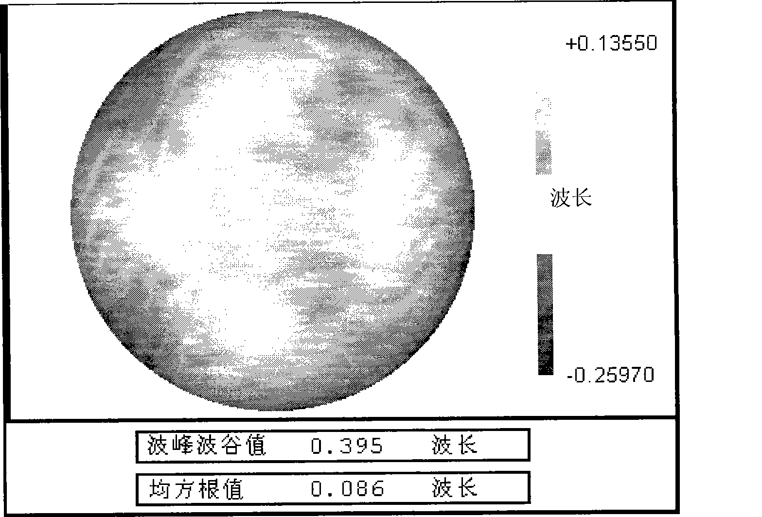
[0052] 2. Use the wave surface interferometer to measure the initial surface error o...


PUM

PropertyMeasurementUnit
diameteraaaaaaaaaa
diameteraaaaaaaaaa

Abstract

The invention discloses a method for splicing and processing an optical element by ion beams, which comprises the following steps of acquiring a removal function by experiments, acquiring a surface-shaped error function by a wave-front interferometer, dividing the processing area of an element, preparing data, confirming area frontiers, correcting the surface-shaped error, establishing a model, calculating out the residency time, processing the first shape correction according to the calculated-out residency time, identifying and error of the first shape correction processing, and repeating the processing step according to the condition of the error identification result until the requirements of the surface-shaped precision is satisfied. The processing method of the invention improves the processing capability of the prior optical processing system, solves the technical problem of processing large-caliber optical elements by the prior small optical processing system and can greatly lower the production cost and the processing cost of the optical processing system.

Description

technical field [0001] The invention relates to a method for processing an optical element by an ion beam, in particular to a splicing processing method for sub-regions of an ion beam processing optical element. Background technique [0002] With the continuous improvement of the performance requirements of modern optical systems, the quality requirements of optical parts are also continuously improved. Modern optical parts are developing in the direction of aspheric surface, light weight and thin shape, and large relative aperture. Strict controls are in place. In order to solve the problems of manufacturing and installing extra-large mirrors, the development of splicing optical systems has been paid more and more attention, so the processing research of special-shaped, light-weight and off-axis aspheric mirrors has been paid more and more attention. At the same time, the number of parts in modern optical systems is huge and the precision is very high. Traditional optical ...

Claims


Application Information

Patent Timeline
Patent Type & Authority Applications(China)
IPC IPC(8): C03C23/00
Inventor 李圣怡解旭辉焦长君戴一帆周林陈善勇
Owner NAT UNIV OF DEFENSE TECH
Why Eureka
Try Eureka