
Optical mask for exposure

A photomask, film-like technology, applied in microlithography exposure equipment, originals for photomechanical processing, photolithography process exposure devices, etc. and other problems, to achieve the effect of reducing parts and reducing production costs

Inactive Publication Date: 2009-07-15
SANEI GIKEN
View PDF1 Cites 8 Cited by
  • Summary
  • Abstract
  • Description
  • Claims
  • Application Information

AI Technical Summary

Problems solved by technology

[0015] The problem caused by the enlargement of the photomask is not only the increase in the cost of making the photomask
In addition, larger photomasks cannot correspond to existing photomask drawing devices.
In order to obtain a compatible drawing device, investment in new equipment is required

Method used


Image

  • Optical mask for exposure
  • Optical mask for exposure
  • Optical mask for exposure

Examples


Embodiment Construction

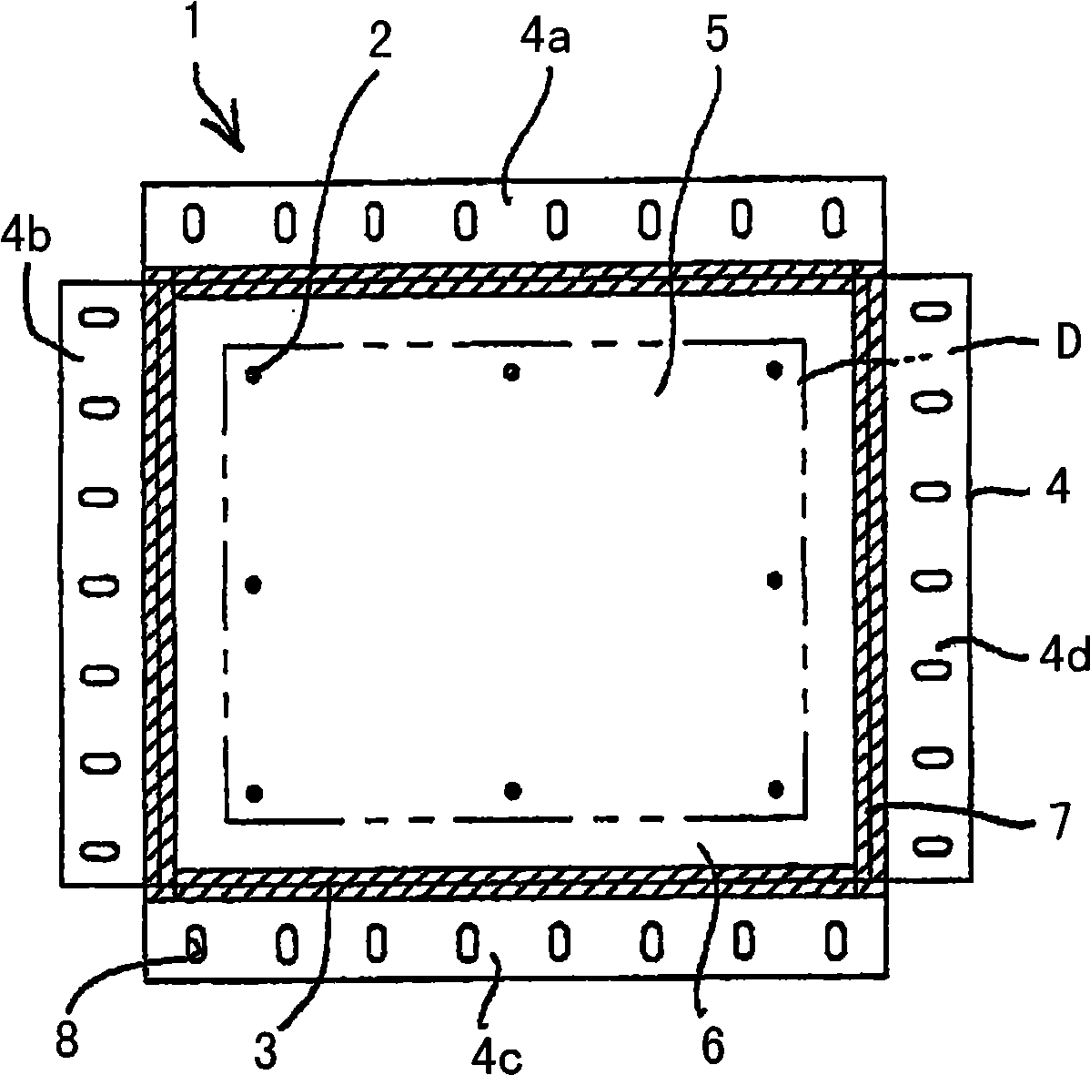
[0041] figure 1 It is a plan view of the photomask 1 according to an embodiment of the present invention. The photomask 1 includes a central part 3 in which a pattern including a plurality of alignment marks 2 is drawn, and a force transmission part 4 which is arranged so as to surround the outer peripheral edge of the central part 3 as a whole. The force transmission part 4 and the central part 3 are made independently.

[0042] The central portion 3 can be divided into an area surrounded by a two-dot chain line D, that is, a pattern display area 5 when a pattern is drawn therein, and an installation area 6 surrounding the area. The central portion 3 is composed of the same or equivalent material as the material forming the existing photomask.

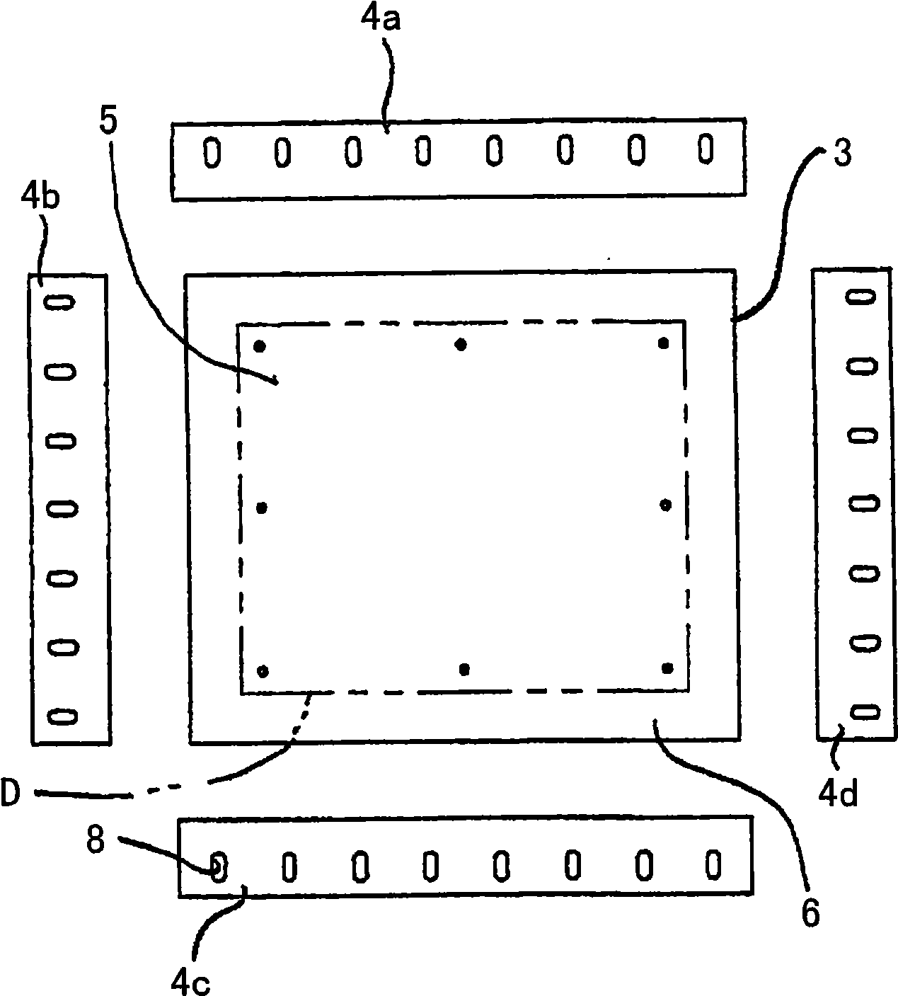
[0043] In this embodiment, as figure 2 As shown, the force transmission part 4 is composed of 4 belt-shaped members 4a-4d independently made on each side of the central part 3. The respective belt-shaped members 4a-4d are joined to each...


PUM


Abstract

The invention relates to a photomask, which is formed by dividing the photomask into a central part depicted with patterns and its surrounding force transfer parts, then bonding, so that it can reduce material costs and avoid investment in new facilities. The photomask (1) is divided into a central part(3) including a pattern display area (5), and a force transmission part (4) surrounding the outer peripheral part of the central part (3). The two parts are mutually jionted by the adhesive tape (7). The force transmission part (4) has a jiont part(hole) (8) connected to a force endowing mechanism, for perform elastic deformation to the central part (3).

Description

Technical field [0001] The present invention relates to a photomask, which is used in an exposure method. In the exposure method, the photomask is elastically deformed by applying force to the periphery of the film-shaped photomask, thereby changing the The size and / or shape of the pattern including a plurality of alignment marks drawn on the above, so that after the photomask and the substrate are aligned, the pattern is transferred to the substrate. Background technique [0002] The above-mentioned exposure method is disclosed in Japanese Patent No. 3402681. based on Figure 5 and Figure 6 Explain its principle. As shown in the figure, a plurality of actuators 102 are provided around the photomask 101 as force applying mechanisms for applying tensile force to the peripheral edge of the photomask 101. The actuator 102 is mounted on the base member 103 so as to surround the photo mask 101. A hook 105 is formed on the movable end 104 of the actuator 102. [0003] On the other han...

Claims


Application Information

Patent Timeline
IPC IPC(8): G03F1/00G03F1/14G03F7/20G03F1/60
CPCF21V17/10G02F1/1336G02F2201/46
Inventor 高木俊博
Owner SANEI GIKEN
Learn More