Electric dry shaver

A dry-type, operating device technology, applied in metal processing and other directions, can solve the problem of limited maximum swing range, and achieve the effect of saving space

Active Publication Date: 2009-07-15
BRAUN AG
View PDF2 Cites 0 Cited by
  • Summary
  • Abstract
  • Description
  • Claims
  • Application Information

AI Technical Summary

Problems solved by technology

Since the drive arranged in the housing must always be connected to the trimming system, the maximum achievable swivel range of the trimming head housing relative to the housing is limited

Method used


Image

  • Electric dry shaver
  • Electric dry shaver
  • Electric dry shaver

Examples


Embodiment Construction

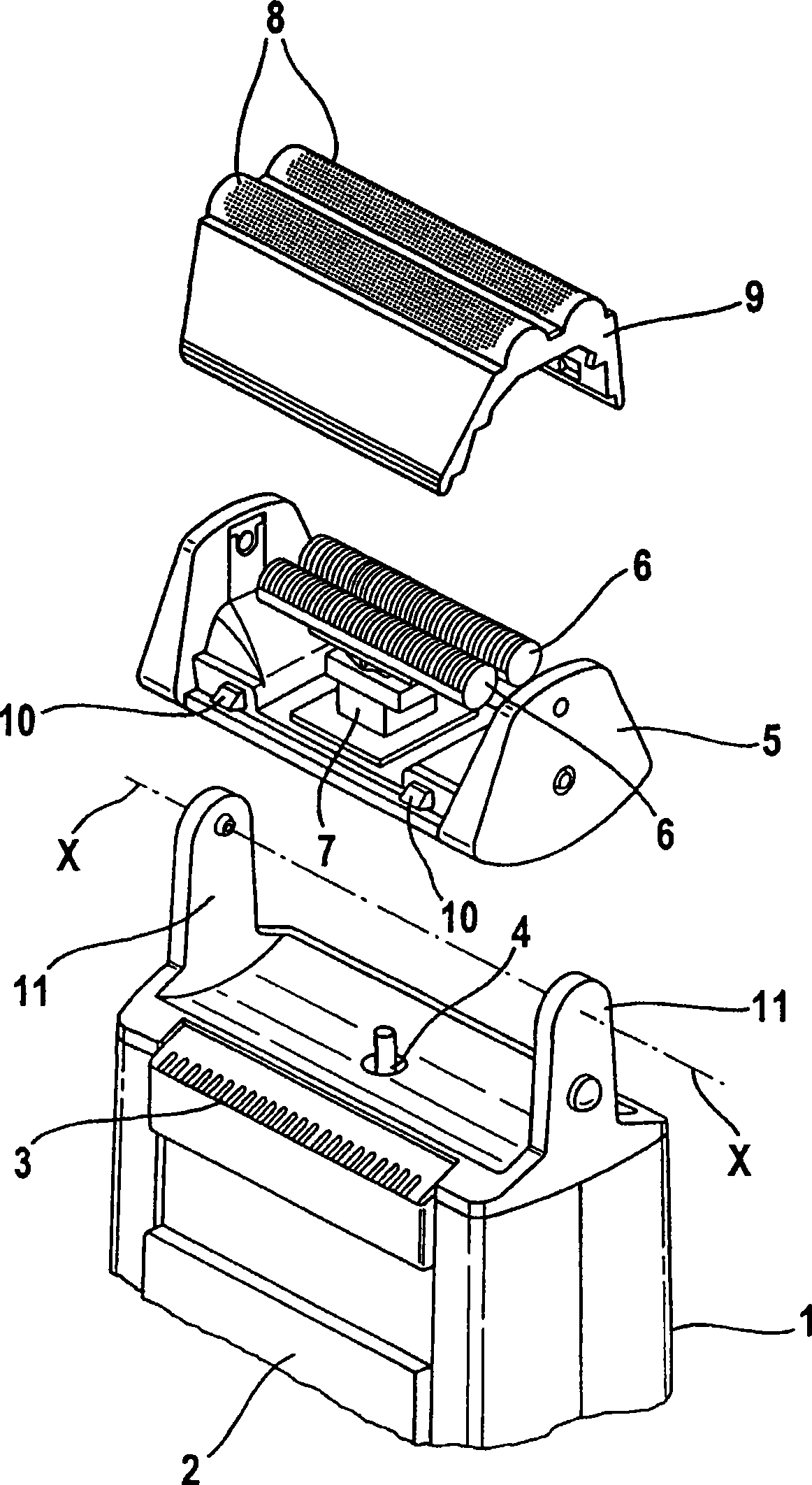
[0019] exist figure 1 The basic structure of a dry shaver with a pivotable trimming head is shown in perspective in the middle, which consists of a housing 1 which accommodates the electric drive and optionally a battery pack, accumulator or the like. On the housing 1 are arranged an on / off device 2 and a trimmer 3 for shortening longer hairs if necessary. At the upper end of the housing, the drive element 4 , which is connected to the electric motor, protrudes from the housing 1 . The pruning head housing 5 accommodates a lower cutter 6 which is formed as a cutter group with a plurality of blades distributed transversely to the direction of oscillation. The lower knife 6 is held by a coupling element 7 which is again connected to the drive element 4 . The upper blade, which is designed as a perforated pruning blade 8 , is held in a frame 9 , which can be connected to the pruning head housing, for example, via latching elements 11 . The trimmer head housing 5 is again suppo...


PUM


Abstract

The invention relates to an electric dry shaver comprising a housing (1) and a shaver head housing (5) connected thereto as to oscillate between two end positions. The shaver head housing (5) carries at least two shaver system (15, 16). At least one shaver system (15, 16) is elastically pretensioned, can be retracted depending on the contact pressure applied by the user, and is received between a position in which it is extended from the shaver head housing and a retracted position. Actuating means (21, 22, 26, 27, 29, 30) in the shaver head housing (5) control, depending on the pivoting angle between the housing (1) and the shaver head housing (5), the height level in the range between the extracted and the retracted position of at least the shaver system (15, 16) that is retractably received between the extracted and the retracted position.

Description

technical field [0001] The invention relates to an electric dry shaver according to the preamble of patent claim 1 . Background technique [0002] Such an electric dry shaver is known from DE-C-36 10 736, wherein this known dry shaver consists of a housing and a trimmer pivotable about a fixed pivot axis relative to the housing The head shell constitutes. The trimming head housing accommodates two linearly oscillating trimming systems running parallel to one another, which can be optimized independently of the orientation of the housing relative to the skin surface due to the pivotable trimming head housing. The two trimming systems can therefore always be applied simultaneously to the skin irrespective of the holding angle of the shaver housing relative to the skin. In addition, the two pruning systems, due to their mounting in the pruning head housing, can react to the contact pressure exerted by the user by means of a corresponding lowering movement by means of the vert...

Claims


Application Information

Patent Timeline
IPC IPC(8): B26B19/04
CPCB26B19/048
Inventor 赖因霍尔德·艾希霍恩德特勒夫·格莱希彼得·容克克里斯托夫·克勒曼迈克尔·奥德默托尔斯滕·珀尔托比亚斯·施瓦茨托马斯·韦尔施泰格马丁·维特于尔根·沃尔夫克里斯托弗·泽古拉
Owner BRAUN AG
Why Eureka
Try Eureka