Method for injecting fuel by means of fuel injection system

Technology of a fuel injection system and fuel injection valve

Inactive Publication Date: 2009-07-15
ROBERT BOSCH GMBH
View PDF1 Cites 7 Cited by
  • Summary
  • Abstract
  • Description
  • Claims
  • Application Information

AI Technical Summary

Problems solved by technology

[0003] A disadvantage of the fuel injection valves known from the aforementioned documents is that, in particular, although the opening movement of the fuel injection valve can take place quickly, the closing movement takes place linearly with a time delay.
This has a detrimental effect on the throttle phase of the fuel injection valve and leads to poor mixture diffusion due to the conical shape of the fuel jet (where the cone angle is small)

Method used


Image

  • Method for injecting fuel by means of fuel injection system
  • Method for injecting fuel by means of fuel injection system
  • Method for injecting fuel by means of fuel injection system

Examples


Embodiment Construction

[0018] Below with the aid of Figure 1-7 The invention is described by way of example.

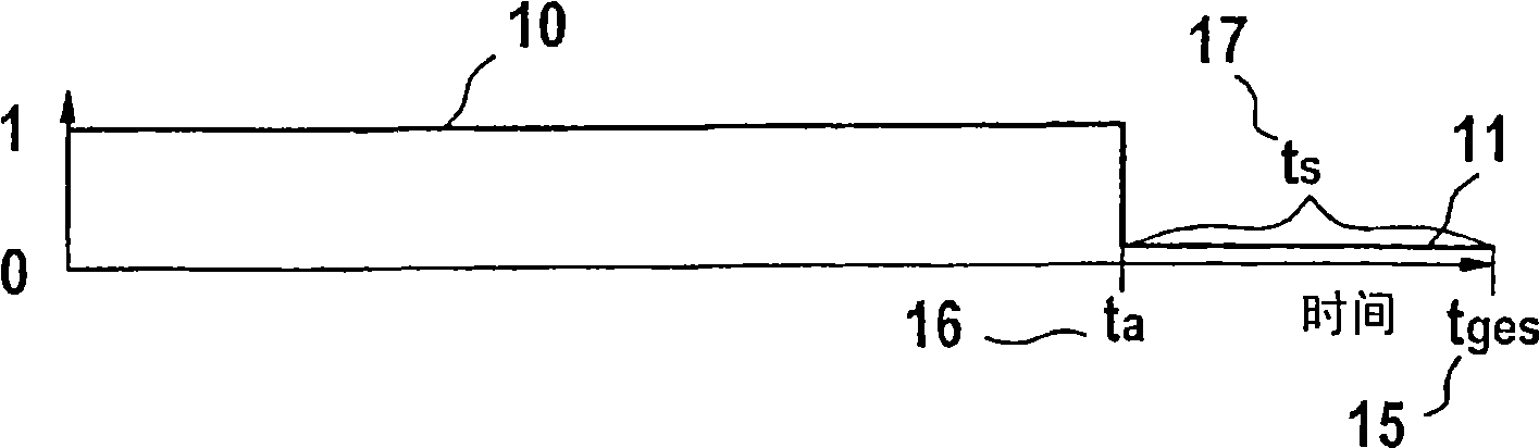
[0019] figure 1 A state-time diagram of an inventive method for targeted injection of fuel is shown, which has an opening phase 10 and a closing phase 11 of a fuel injection valve 2 . In a first method step, a controller 9, which is an integral part of the fuel injection system 1 according to the invention, determines that a total time interval is provided for the opening phase 10 and the closing phase 11 of the fuel injection valve 1 t ges 15. During the time interval t ges Within 15 (this time interval is based on a time interval t a 16 and a time interval t s 17 results in) an opening phase 10 and a closing phase 11 are determined for the fuel injector 2 which correspond to the time interval t a 16 and the state "1" recorded on the ordinate of the state-time diagram, the closing phase corresponds to the time interval t s 17 and the state "0" described on the abscissa of the stat...


PUM


Abstract

A fuel injection system (1) for the targeted injection of fuel, comprising a fuel injection valve (2) having a solenoid coil (3), which cooperates with an armature (5) supplied by a return spring (4), the armature forming an axially displaceable valve part together with a valve needle (6), and a control device (9). The control device (9) defines an opening phase (10) having a first holding current (12), and a closing phase (11) beginning after the opening phase (10) and having a second holding current (13) for the fuel injection valve (2), wherein the current characteristic in the solenoid coil (3) is defined during the closing phase (11) of the fuel injection valve (2) such that the magnetic field generated by the second holding current (13) flowing through the solenoid coil (3) brings about a certain magnetic force, such that the valve needle (6) thus experiences a defined stroke (14) that is different from zero, and steadily maintains the same over a defined period of time.

Description

technical field [0001] The invention relates to a method for injecting fuel by means of a fuel injection system according to the preamble of claim 1 and to a fuel injection system according to the invention according to the preamble of claim 12 . Background technique [0002] DE 198 55 547 A1 discloses a fuel injector having a valve slide, an exciter coil, an armature which can be biased against a return spring in a direction of travel via the exciter coil, and a valve needle. The valve needle is fixedly connected both to the armature and to a valve closing body (which cooperates with a stationary sealing seat) and forms a movable valve unit. An auxiliary body is arranged on the valve needle between the armature and the valve closing body, which is movable relative to the valve needle. The valve needle is designed with a drive so that when the auxiliary body moves in the direction of travel, the valve needle can be accelerated in the same direction and a rapid opening of th...

Claims


Application Information

Patent Timeline
Patent Type & Authority Applications(China)
IPC IPC(8): F02D41/20F02M51/06
CPCF02M45/12F02M61/1833F02M51/0617F02M51/061F02D41/20
Inventor A·施托希C·海姆格特纳
Owner ROBERT BOSCH GMBH
Why Eureka
Try Eureka