Eureka AIR delivers breakthrough ideas for toughest innovation challenges, trusted by R&D personnel around the world.

Implementing method and apparatus for radio frequency module in multiple antenna

A technology of a radio frequency module and an implementation method, applied in the field of network communication, can solve the problems of not using stock, reducing system performance, and inflexible configuration, and achieving the effects of improving module integration, improving system performance, and reducing the number of modules

Active Publication Date: 2009-07-22
HUAWEI TECH CO LTD
View PDF0 Cites 2 Cited by
  • Summary
  • Abstract
  • Description
  • Claims
  • Application Information

AI Technical Summary

Problems solved by technology

[0004] It can be seen from the above solutions of the prior art that corresponding modules need to be designed according to different requirements, so that there are many types of modules, and the relative cost is relatively high without using stocking; at the same time, the entire module needs to be replaced when the live network is upgraded, making The configuration is not flexible enough, which reduces the system performance

Method used


Image

  • Implementing method and apparatus for radio frequency module in multiple antenna
  • Implementing method and apparatus for radio frequency module in multiple antenna
  • Implementing method and apparatus for radio frequency module in multiple antenna

Examples


Embodiment 1

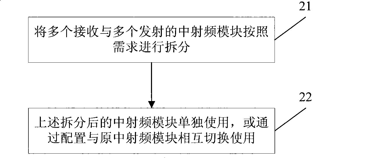
[0021] Embodiment 1: Embodiment 1 of the present invention provides a method for implementing a radio frequency module in a multi-antenna, such as figure 2 Shown is a schematic flow chart of the method provided in this embodiment 1, the method comprising:

[0022] Step 21: Split multiple receiving and multiple transmitting mid-radio frequency modules according to requirements.

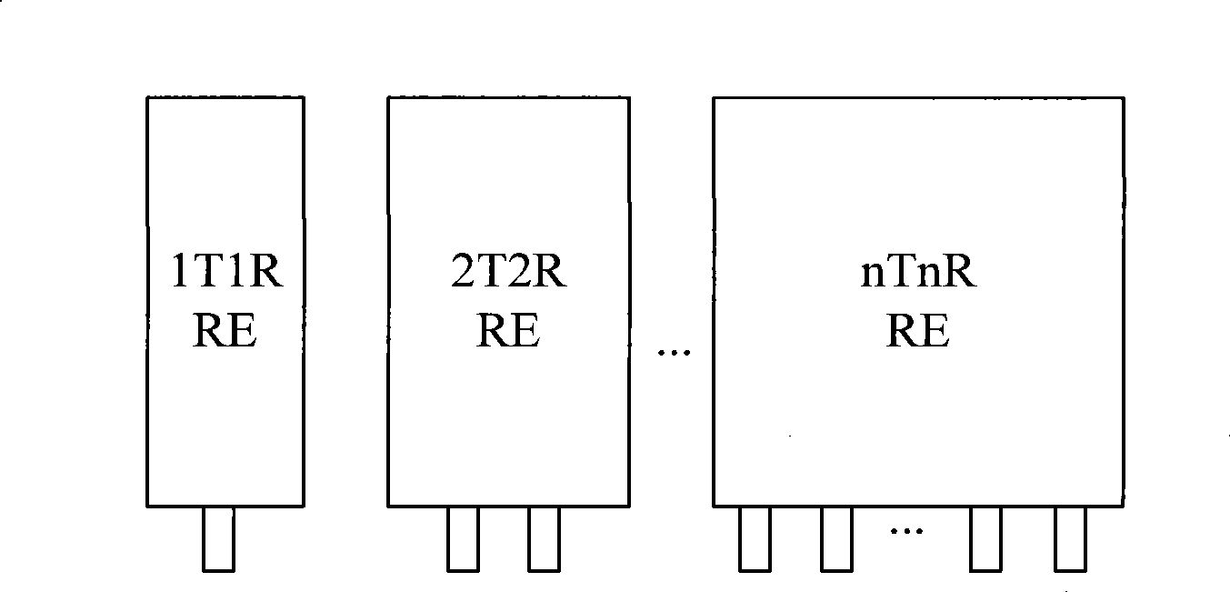
[0023] In this step, multiple receiving and multiple transmitting intermediate radio frequency modules can be set as n receiving and n transmitting intermediate radio frequency modules, where n is an integer; according to actual use requirements, the n receiving and transmitting modules can be The n transmitting mid-radio frequency modules are split into m receiving and m transmitting mid-radio frequency modules, where m is also an integer and n is an integer multiple of m.

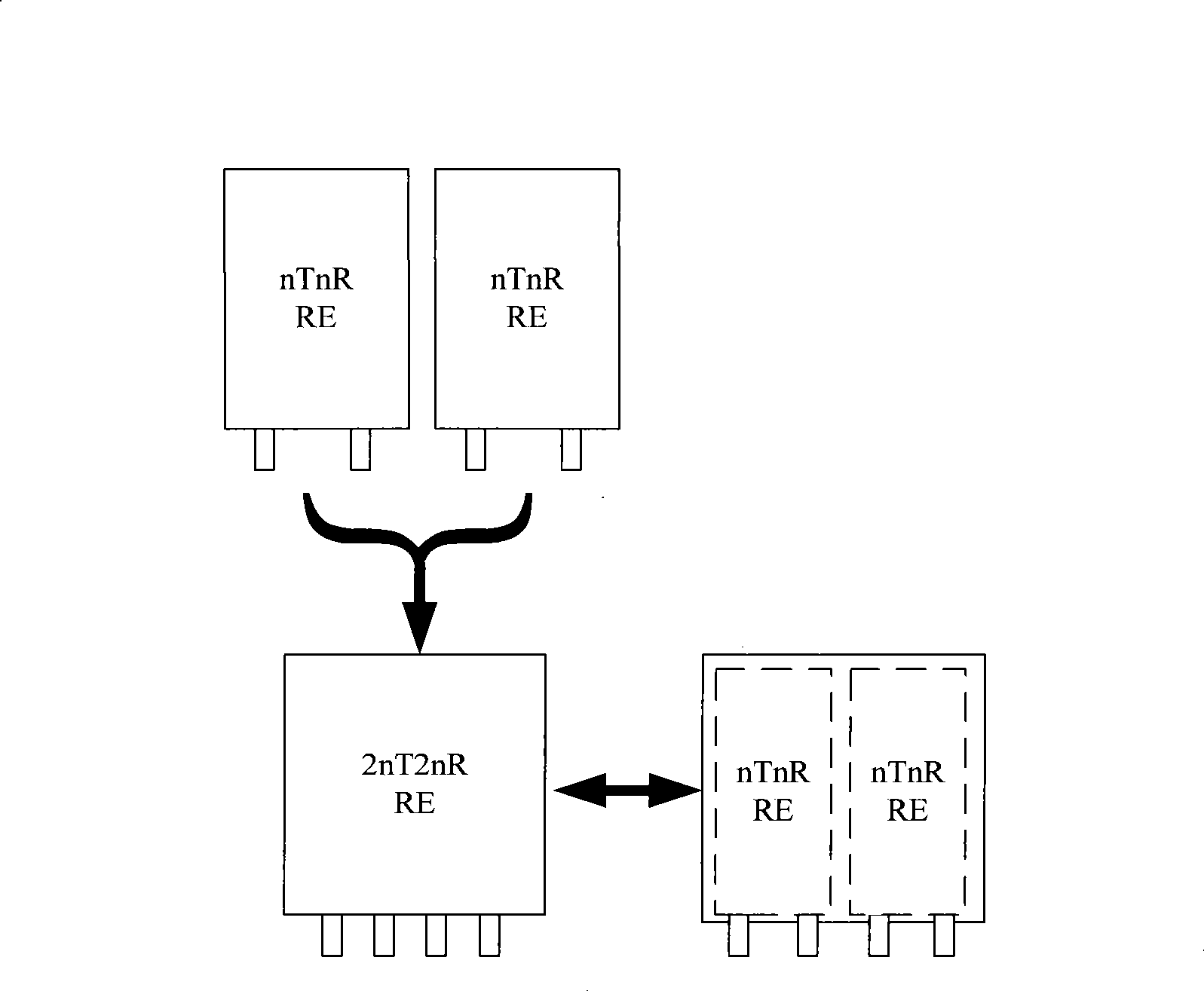
[0024] For example, if image 3 Shown is a schematic diagram of the RF module RE in 2nT2nR being split into two RF modules in...

Embodiment 2

[0037] Embodiment 2: Embodiment 2 of the present invention provides a device for implementing a radio frequency module in a multi-antenna, such as Figure 7 Shown is a schematic structural diagram of the device provided in Embodiment 2, the device includes a module splitting unit and a module switching unit, wherein:

[0038] The module splitting unit is used to split n receiving and n transmitting intermediate radio frequency modules into m receiving and m transmitting intermediate radio frequency modules; wherein, n and m are both integers, and n is an integer of m times; the split into m receiving and m transmitting middle radio frequency modules can be used alone.

[0039] The module switching unit is used to switch between the n receiving and n transmitting intermediate radio frequency modules and the divided m receiving and m transmitting intermediate radio frequency modules through configuration control.

[0040] In addition, the above-mentioned module splitting unit m...


PUM


Abstract

The invention embodiment provides an implementing method and apparatus of multiple-aerial intermediate radio frequency module. n receiving and n transmitting intermediate radio frequency modules are dismantled into m receiving and m transmitting intermediate radio frequency modules; wherein, n and m are all integers, and n is integer times of m; the dismantled m receiving and m transmitting intermediate radio frequency module are used by single, or used for switching with each other by configuring the n receiving and the n transmitting intermediate radio frequency modules, thereby reducing the module amounts and improving the module integration degree; meanwhile, when the present network is upgraded, only the corresponding modules are increased without changing the whole module in the present network, thereby the configuration is more flexible, and the system performance is improved.

Description

technical field [0001] The invention relates to the field of network communication, in particular to a method and device for realizing a radio frequency module in a multi-antenna. Background technique [0002] At present, in the field of mobile communication, multi-antenna technology is a common means to solve system capacity problems. The so-called multi-antenna technology means that both the sender and receiver use multiple antennas to transmit and receive. Through appropriate transmission signal form and receiver design, the Multi-antenna technology can increase the capacity of the system without significantly increasing the cost of the wireless communication system. [0003] In the prior art, the multi-antenna technology can generally be nTnR (n Transceiver n Receiver, n receivers and n transmitters), but not any multi-antenna technology can be applied to all scenarios. For example, in the WiMAX 802.16E system, when the multi-antenna application is 4T4R, due to the rela...

Claims


Application Information

Patent Timeline
IPC IPC(8): H04B7/04
Inventor 周健江胜峰
Owner HUAWEI TECH CO LTD
Why Eureka
Eureka Blog
Learn More