Sealed terminal device for electric compressor

An electric compressor and a sealed terminal technology, applied in the field of electric compressors, can solve the problems of decreased electrical insulation of terminals, troublesome fixing of metal cages and sealed terminals, difficult installation of sealed terminal devices, etc., and achieve the effect of ensuring sealing.

Inactive Publication Date: 2009-07-22
SANDEN CORP
View PDF1 Cites 24 Cited by
  • Summary
  • Abstract
  • Description
  • Claims
  • Application Information

AI Technical Summary

Problems solved by technology

[0006] However, in order to ensure the close contact between the metal holder and the glass, the use of the above-mentioned glass not only requires the metal holder to be nickel-plated, but also the fixing of the metal holder and the sealing terminal is very troublesome.
Therefore, for the hermetic terminal device using glass, it is difficult to mo

Method used


Image

  • Sealed terminal device for electric compressor
  • Sealed terminal device for electric compressor
  • Sealed terminal device for electric compressor

Examples


Embodiment Construction

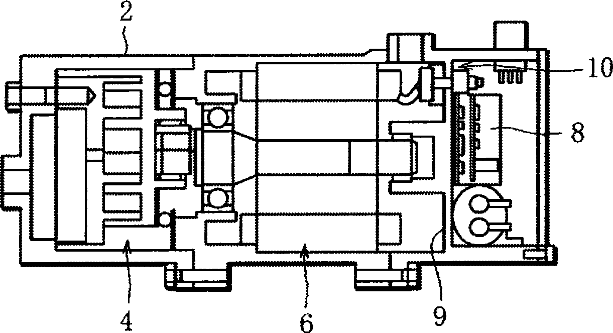
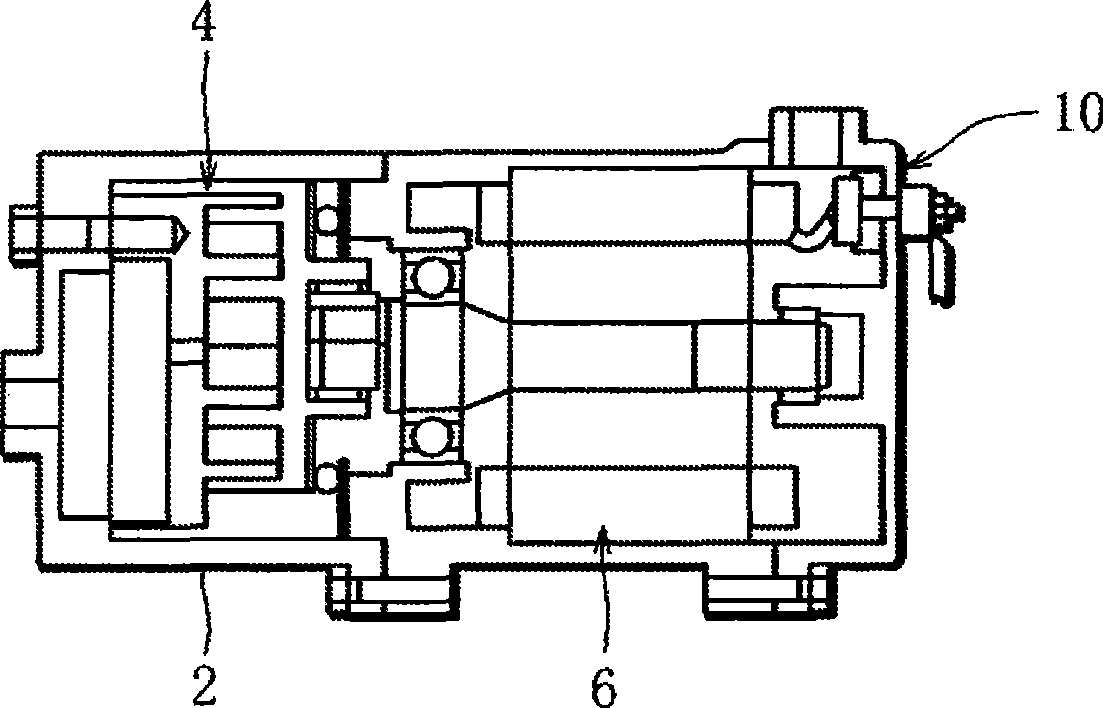
[0026] figure 1 and figure 2 Each shows an electric compressor to which the present invention is applied. These electric compressors all include a metal casing 2 , a compression unit 4 and an electric motor 6 accommodated in the casing 2 . figure 1 and figure 2 The compression unit 4 is represented as a scroll unit.

[0027] figure 1 The compressor further includes a power supply control board 8 accommodated in the casing 2 . The control board 8 has an inverter and controls the power supply to the electric motor 6 and the driving of the electric motor 6 . Specifically, in figure 1 The housing 2 is provided with a partition wall 9 that partitions the housing 2 into a chamber for accommodating the compression unit 4 and the electric motor 6 and a chamber for accommodating the control board 8 .

[0028] on the other hand, figure 2 compressor with figure 1 The difference of the compressor is that there is no above-mentioned partition wall 9. However, figure 1 and f...


PUM


Abstract

A sealed terminal device for a motor-driven compressor has an electrically insulating terminal holder (12) to be attached to the housing wall (2a) of the motor-driven compressor, a plurality of sealed terminals (18) held in the terminal holder (12), for penetrating the housing wall (2a) with play to the housing wall (2a), and a groove (40) or cavity (38) formed in the terminal holder (12) to increase a creepage distance for insulation between the sealed terminals.

Description

technical field [0001] The present invention relates to an electric compressor incorporating an electric motor, and more particularly to a hermetic terminal device for establishing electrical connection between the electric motor and the outside. Background technique [0002] Such an electric compressor includes a casing, a compression unit and an electric motor accommodated in the casing (Patent Document 1). The compression unit is driven by an electric motor and performs a series of processes from suction of working fluid through compression to discharge. [0003] The above compressor further has a hermetic terminal device for establishing electrical connection between the electric motor and the outside, and the hermetic terminal device has a plurality of hermetic terminals. These hermetic terminals penetrate through the wall of the casing in an airtight manner, and have both ends protruding toward the inside and outside of the casing, respectively. [0004] Patent Docum...

Claims


Application Information

Patent Timeline
IPC IPC(8): F04B39/00
CPCH02G3/22F04C23/008H01R13/521F04C2240/803F04C18/0215H02G15/013H02K5/225H02K5/10
Inventor 田口正则尾坂昌彦押尾英一龟山和彦齐藤晓
Owner SANDEN CORP
Why Eureka
Try Eureka