Transmission apparatus for air conditioning apparatus

A transmission device and reconciliation technology, applied in space heating and ventilation, transmission systems, electrical components, etc., can solve problems such as limiting the number of machines, abnormal communication, and difficulty in expanding communication data, and achieve the effect of reducing common noise

Inactive Publication Date: 2009-07-22
DAIKIN IND LTD
View PDF0 Cites 8 Cited by
  • Summary
  • Abstract
  • Description
  • Claims
  • Application Information

AI Technical Summary

Problems solved by technology

As a result, the communication waveforms of the other indoor units 40 and 40 connected in the middle of the route of the internal and external transmission line 10B are deformed and communication abnormalities may occur.
[0006] Also, since the data transmission path of the air conditioner is built on the same main line, if any part of the transmission path fails (for example, a short circuit in the transmission path, induction of noise), it will have a bad effect on the entire system
In addition, the communication data transmitted from the concentrated transmission line 10A and the internal and external transmission lines 10B all flow on the centralized transmission line 10A, so the communication traffic may be increased.
As a result, there will be problem...

Method used


Image

  • Transmission apparatus for air conditioning apparatus
  • Transmission apparatus for air conditioning apparatus
  • Transmission apparatus for air conditioning apparatus

Examples


Embodiment approach 1

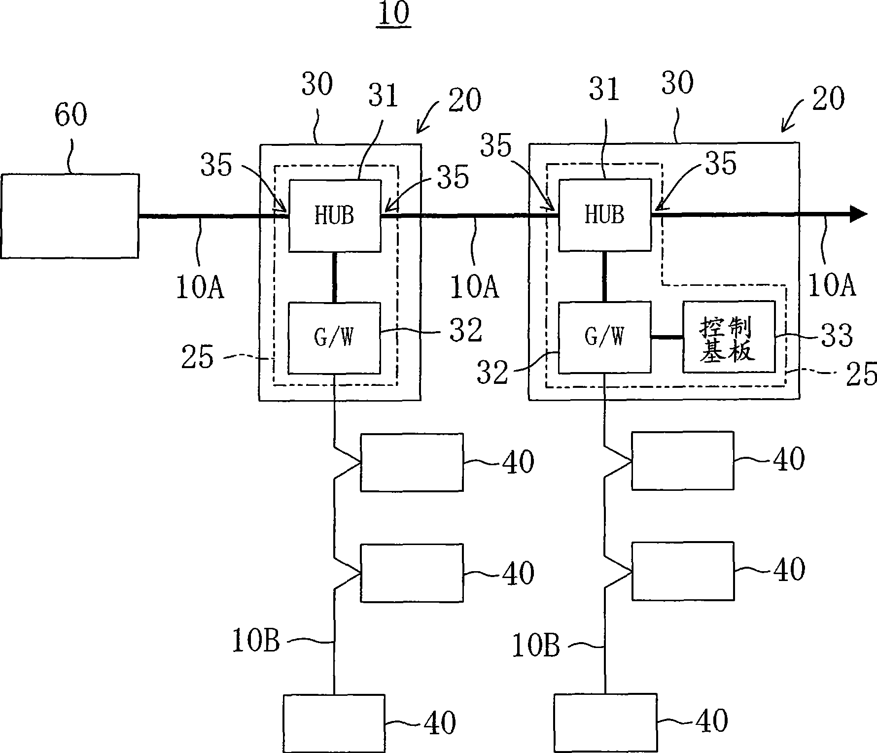
figure 1 , is a schematic diagram showing the configuration of the conveying device of the air-conditioning apparatus according to Embodiment 1 of the present invention. Such as figure 1 As shown, the conveying device 10 of the air conditioner includes two air-conditioning units 20, 20, and each group of the two air-conditioning units 20, 20 is connected to an outdoor unit 30 by refrigerant pipes connected in parallel. Three indoor units 40, 40, 40 are formed.

[0033] Still, although not shown in the figure, the above-mentioned outdoor unit 30 includes at least an outdoor heat exchanger having a compressor, a four-way switching valve, and a fan, and an outdoor electric expansion valve, and indoor units 40, 40, 40, although not shown shown, including an indoor heat exchanger with at least an indoor electric expansion valve and a fan. In addition, the refrigerant circulation circuit is configured in such a manner that the refrigerant circulation direction in the cooling ope...

Embodiment approach 2

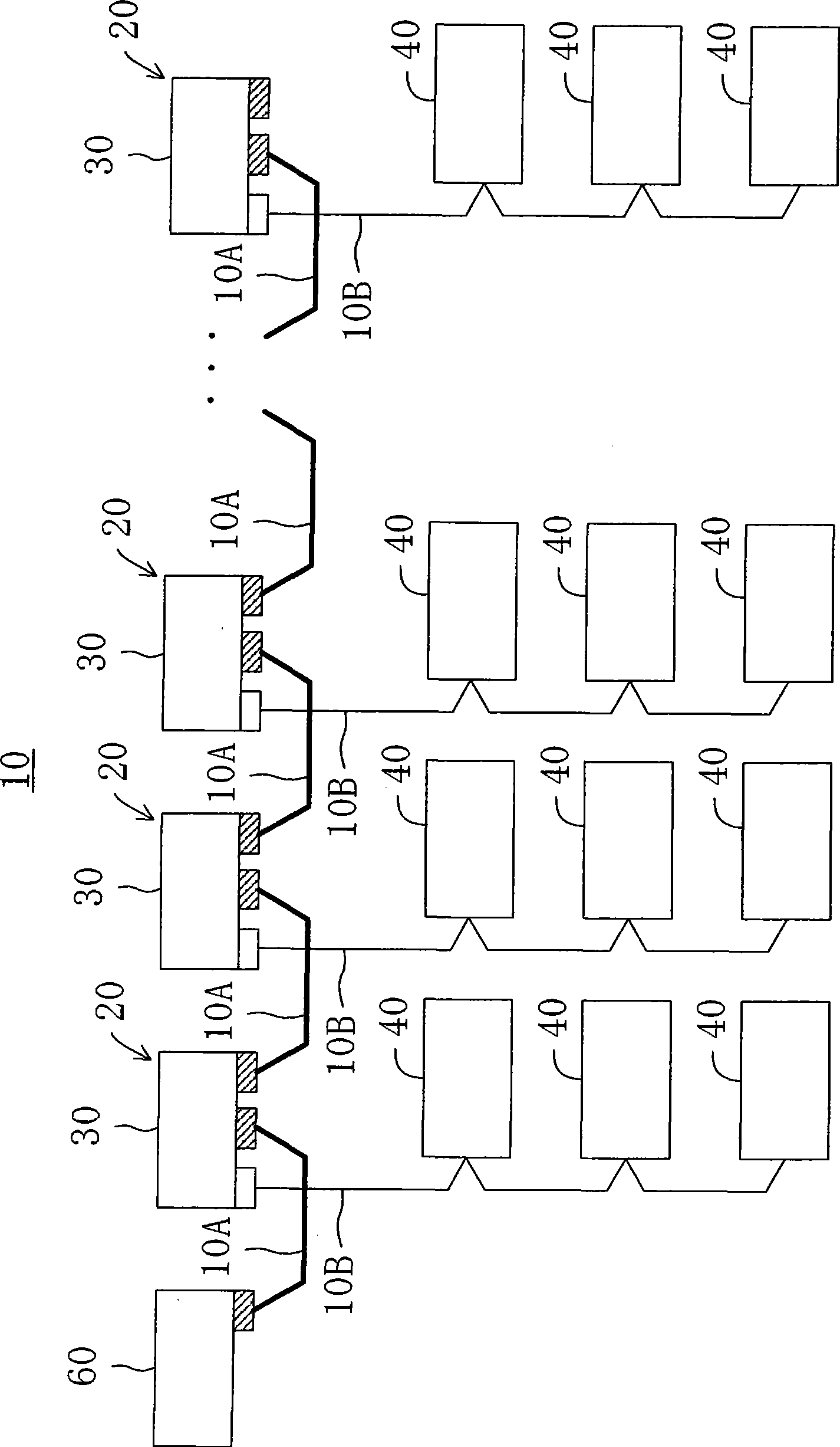
Figure 5 , is a schematic diagram showing the configuration of the conveying device of the air-conditioning apparatus according to Embodiment 2 of the present invention. The difference from the above-mentioned first embodiment is that the connection of the collective transmission line 10A is a spanning tree method. Hereinafter, the same parts as those of the first embodiment are given the same reference numerals, and only the difference will be described.

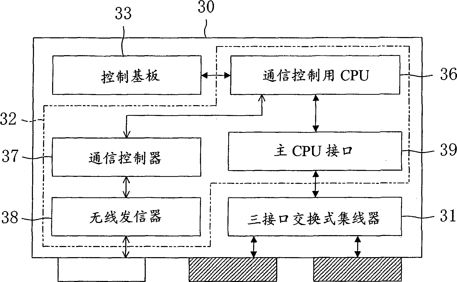
[0062] Figure 5 , is a state in which a plurality of outdoor units 30, 30, . Still, as long as it is a normal machine operation, the number of openings of the switching hub 31 in the outdoor unit 30 is sufficient, but in the second embodiment, three openings are used for maintenance or for an adapter for connecting to a LAN in the machine. and also, Figure 5 In , the main CPU interface is not included, and the illustration of the indoor unit 40 is omitted.

[0063] Such as Figure 5 As shown, the transmission device ...


PUM


Abstract

To minimize the influence on a whole system caused by abnormal communication occurring at a part of a transmission line, an air conditioning apparatus and a transmission apparatus for the air conditioning apparatus are provided. A plurality of air conditioning units (20, 20) are connected by daisy chain system by using switching hubs (31) incorporated in outdoor units (30). The air conditioning units are connected by permitting data transmission on a center transmission line (10A) and that on an indoor-outdoor transmission line (10B) to be separately performed, by gateways (32) connected to the switching hubs (31).

Description

technical field [0001] The present invention relates to a conveying device of an air conditioning device for centrally controlling a plurality of air conditioning units. Background technique [0002] So far, as a transmission device for multiple air conditioners used in buildings, one outdoor unit is connected to multiple indoor units by internal and external transmission lines to form an air conditioning unit. The method of controlling the unit is known (for example, refer to Patent Document 1). [0003] In the transmission device described in Patent Document 1, the centralized control unit and the outdoor unit are connected by a main line through a centralized transmission line. Here, one communication interface can be used by making the communication control procedure of the centralized transmission line and the communication line of the indoor unit the same. In addition, inside the outdoor unit, the centralized transmission line and the communication line of the indoor...

Claims


Application Information

Patent Timeline
IPC IPC(8): F24F11/02
CPCF24F2011/0067F24F11/006H04L12/283H04L2012/285H04L12/40006F24F11/30F24F11/62F24F11/54F24F11/56
Inventor 冈野贵史玉腰光市郎堂前浩
Owner DAIKIN IND LTD
Why Eureka
Try Eureka