Light guiding device for thin type display and the thin type display thereof

A light guide device and display technology, applied to static indicators, light guides of lighting systems, light guides, etc., can solve problems such as uneven distribution of light on the light guide plate, difficulty in combining light sources, and light leakage

Inactive Publication Date: 2009-07-29
AU OPTRONICS CORP
View PDF0 Cites 15 Cited by
  • Summary
  • Abstract
  • Description
  • Claims
  • Application Information

AI Technical Summary

Problems solved by technology

The problem with this type of curved display 1 is that the light emitted by the light emitting diodes 103 arranged on the side 11 travels in a straight line, and cannot turn along the curvature of the light guide plate, so that the light distribution on the light guide plate is uneven. Uniform, resulting in light leakage at large angles
[0005] In addition, there are known techniques that have tried on the less bright side, such as: figure 1 An additional row of light source devices is added to the end edge of the side 12 to increase the light source distribution on the side, but another problem arises that it is difficult to combine two different light sources.

Method used


Image

  • Light guiding device for thin type display and the thin type display thereof
  • Light guiding device for thin type display and the thin type display thereof
  • Light guiding device for thin type display and the thin type display thereof

Examples


Embodiment Construction

[0028] After referring to the accompanying drawings and the implementation methods described later, those skilled in the art can understand other objectives of the present invention, as well as the technical means and implementation aspects of the present invention.

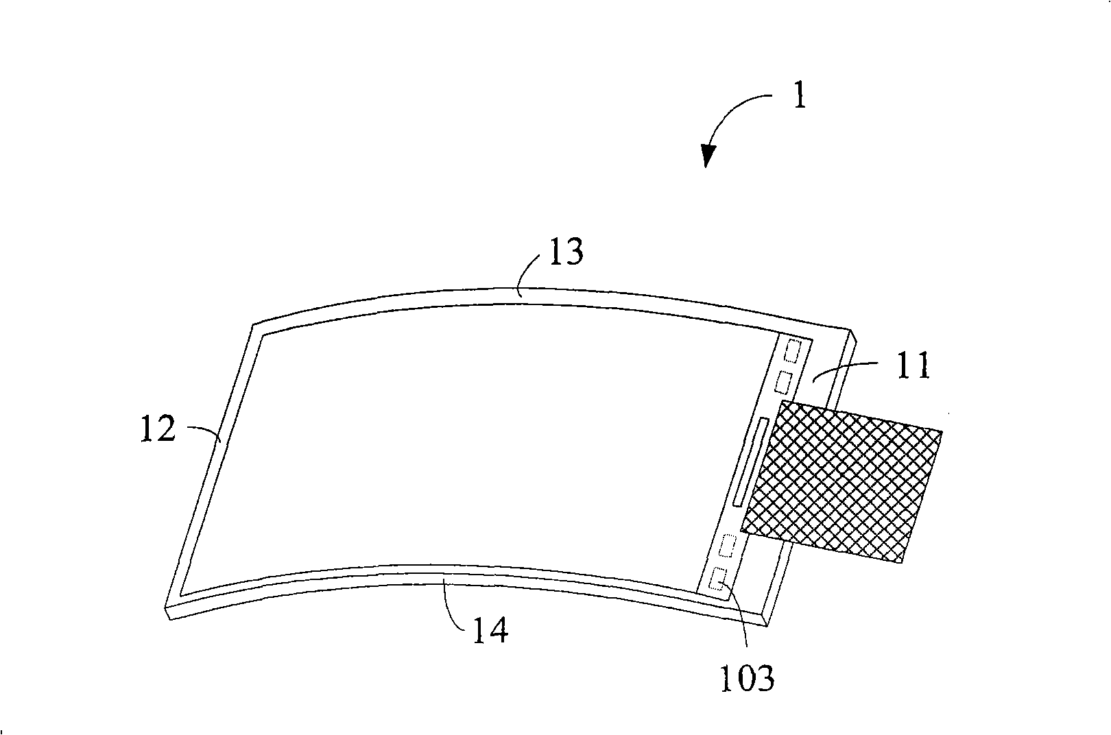
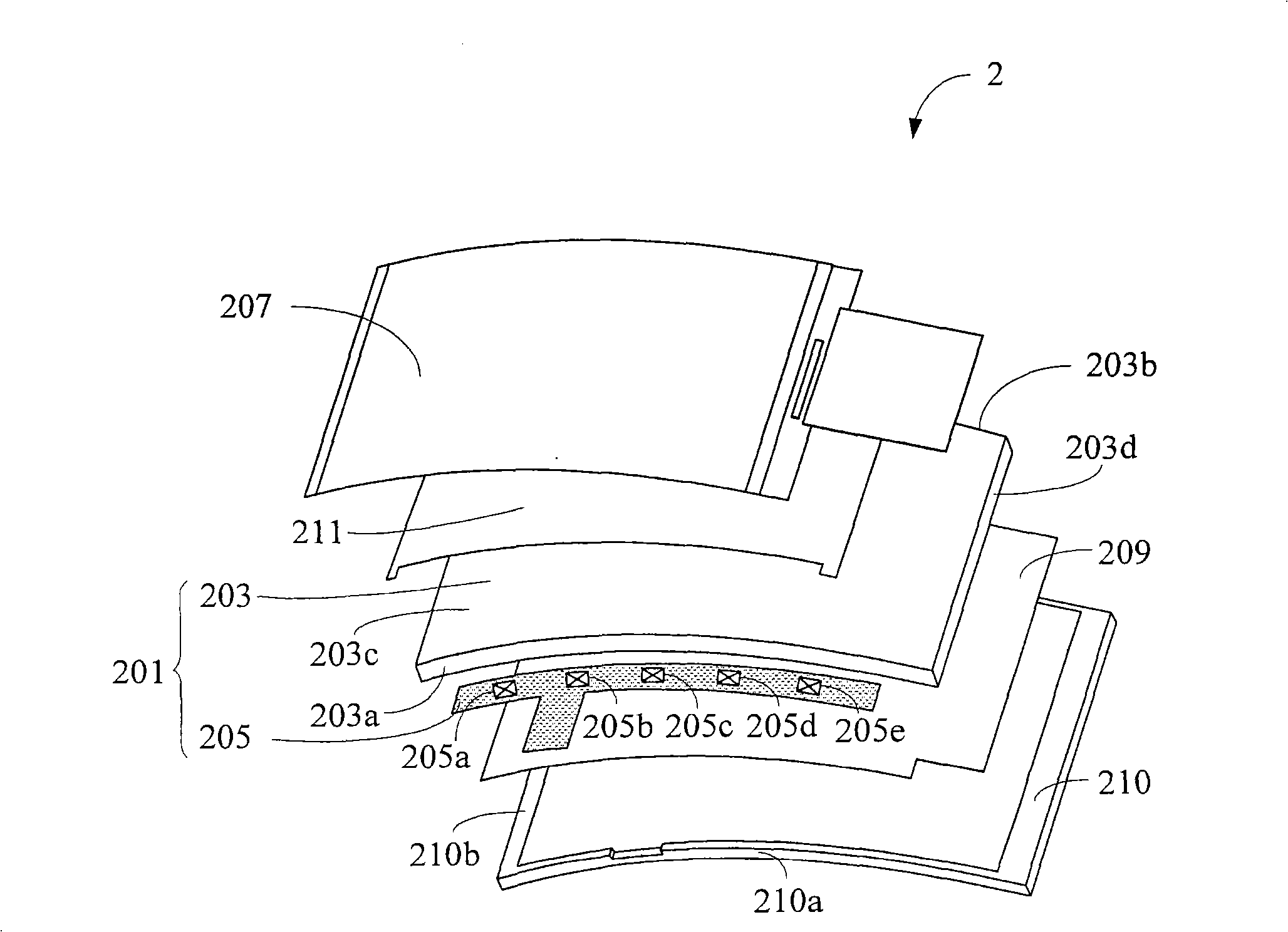
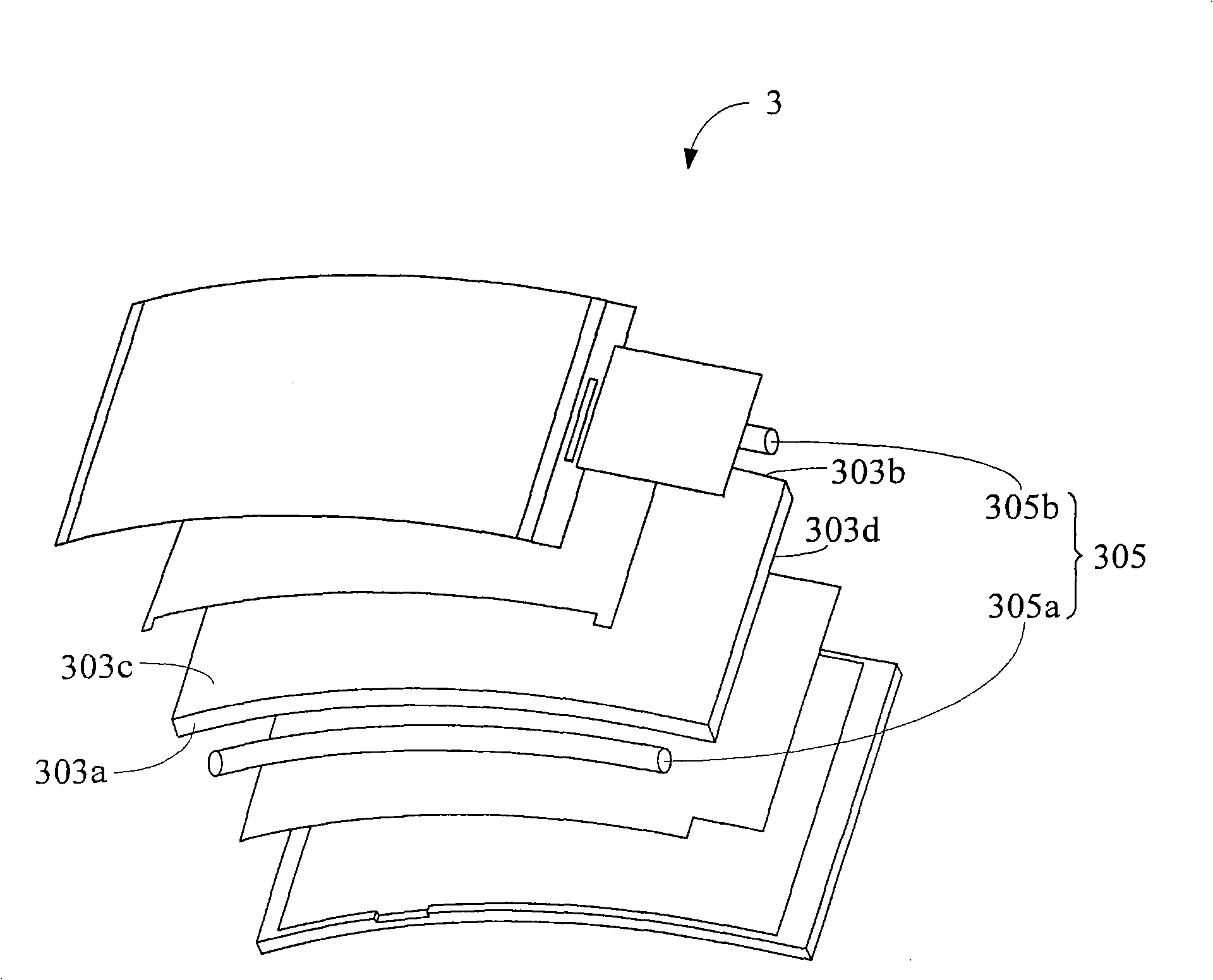
[0029] Please refer to figure 2 , which shows a schematic diagram of a thin display 2 in the first embodiment of the present invention. The thin display 2 includes a light guide device 201 , a panel 207 , a reflector 209 , a frame 210 and an optical film 211 . The thin display 2 in this embodiment has an arc shape, and the curvature of the arc shown in the drawings is only an example rather than limiting the present invention.

[0030] The frame 210 has two opposite arc-shaped side frames 210a and opposite side frames 210b. The light guide device 201 is arranged inside the frame 210. The light guide device includes a light guide plate 203 and a light source device 205, wherein The light guide plate 203 include...


PUM


Abstract

The invention discloses a light conducting device for a thin-type display and a thin-type display thereof. The thin-type display comprises a light conducting device, a panel and a frame, wherein, the frame is equipped with two opposite arc-shaped side frames and two opposite side frames, the light conducting device is equipped with a light conducting plate and a light source device; the light conducting plate is equipped with a top camber, a bottom camber, a first arc-shaped side and a second arc-shaped side; the top camber and the bottom camber are relatively connected with the first arc-shaped side and the second arc-shaped side on the two sides of the top camber and the bottom camber, the first arc-shaped side and the second arc-shaped side are relatively arranged in the two arc-shaped side frames; the light source device is arranged between one of the two arc-shaped sides and one of the two arc-shaped side frames; and the panel is arranged in the frame and on the light conducting device.

Description

technical field [0001] The present invention relates to a display, and more specifically, the present invention relates to a curved display, especially to a light guide device for a thin display and the thin display. Background technique [0002] With the progress of the times, the monitor has also evolved from the traditional cathode ray tube screen (Cathode Ray Tube; CRT) to today's common liquid crystal display (Liquid Crystal Display; LCD). Thin, light in weight, less power consumption, and low radiation, liquid crystal displays have largely replaced cathode ray tube screens and become the mainstream of home displays. [0003] Most of the current liquid crystal displays are vertical liquid crystal displays. If the user looks at the liquid crystal display from the top to the bottom, the user will easily experience visual fatigue after using it for a long time. In view of this, some manufacturers have designed liquid crystal displays with curved curved surfaces to improve...

Claims


Application Information

Patent Timeline
Patent Type & Authority Applications(China)
IPC IPC(8): F21V8/00G02B6/00G02F1/133
Inventor 郭汉斌苏震益
Owner AU OPTRONICS CORP
Why Eureka
Try Eureka