Eureka AIR delivers breakthrough ideas for toughest innovation challenges, trusted by R&D personnel around the world.

Projector

A technology for projectors and projections, which is applied in the field of projectors, can solve the problems of large number of parts and difficulty in making the projection position adjustment device small and lightweight, and achieve the effect of reducing the number of parts

Inactive Publication Date: 2009-07-29
SEIKO EPSON CORP
View PDF1 Cites 4 Cited by
  • Summary
  • Abstract
  • Description
  • Claims
  • Application Information

AI Technical Summary

Problems solved by technology

[0007] However, in the projection position adjustment device described in Patent Document 1, the first movable plate and the second movable plate are supported by an auxiliary plate in addition to the fixed plate, and the first movable plate is brought into contact with the fixed plate by a loading member. , so the number of components is large, and it is difficult to reduce the size and weight of the projection position adjustment device

Method used


Image

  • Projector
  • Projector
  • Projector

Examples


Embodiment Construction

[0044] Hereinafter, one form of embodiment of the present invention will be described with reference to the drawings.

[0045] [Appearance composition]

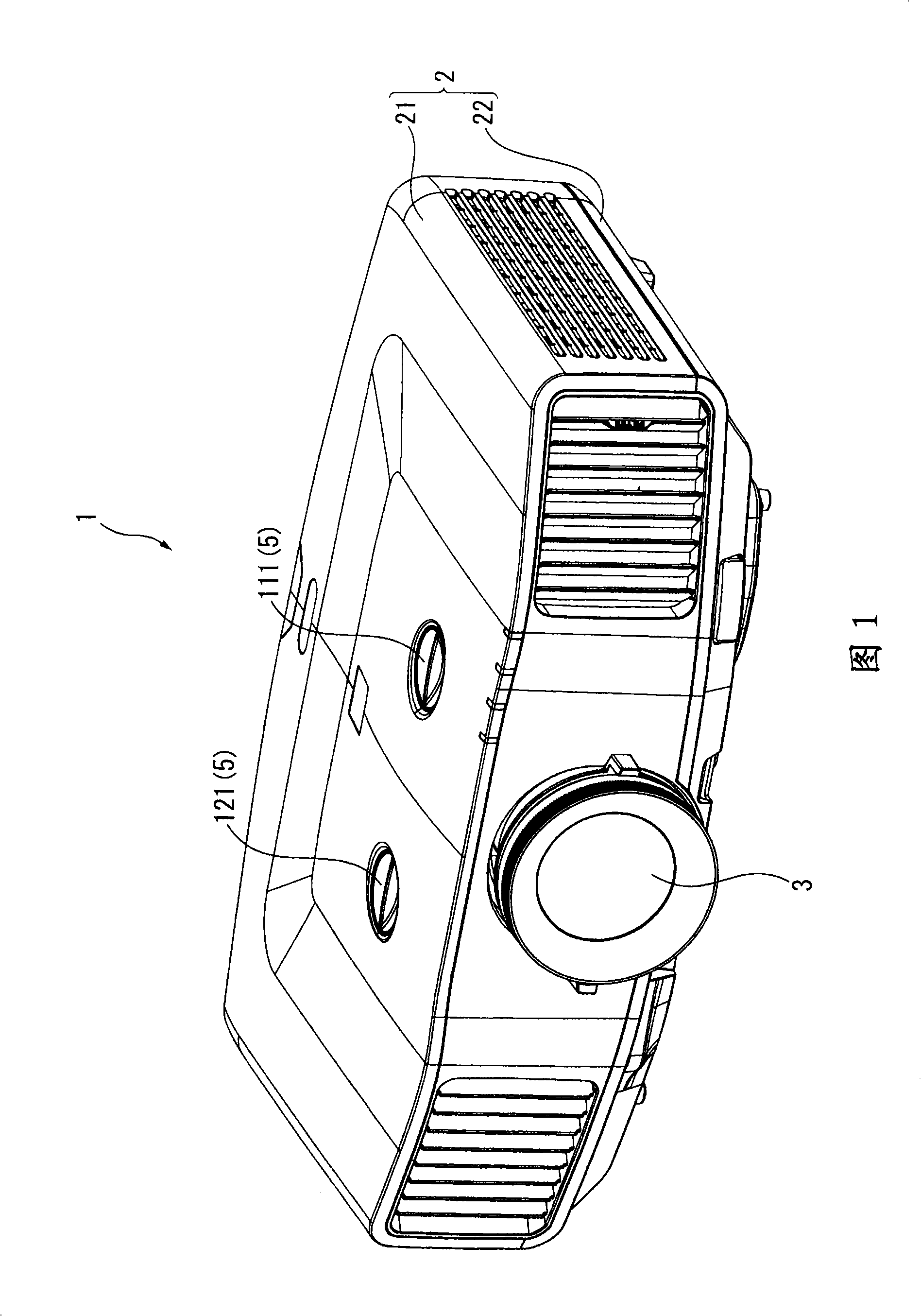
[0046] FIG. 1 is a side view showing the appearance of a projector 1 in this embodiment. Specifically, FIG. 1 is a side view of a state in which the projector 1 is installed on a table or the like, as seen from the front and upper side.

[0047] In addition, "up", "down", "left", and "right" described below correspond to up, down, left, and right in the drawings. In addition, the "front" and "rear" described below also correspond to the front and rear in the drawing in FIG. 1 .

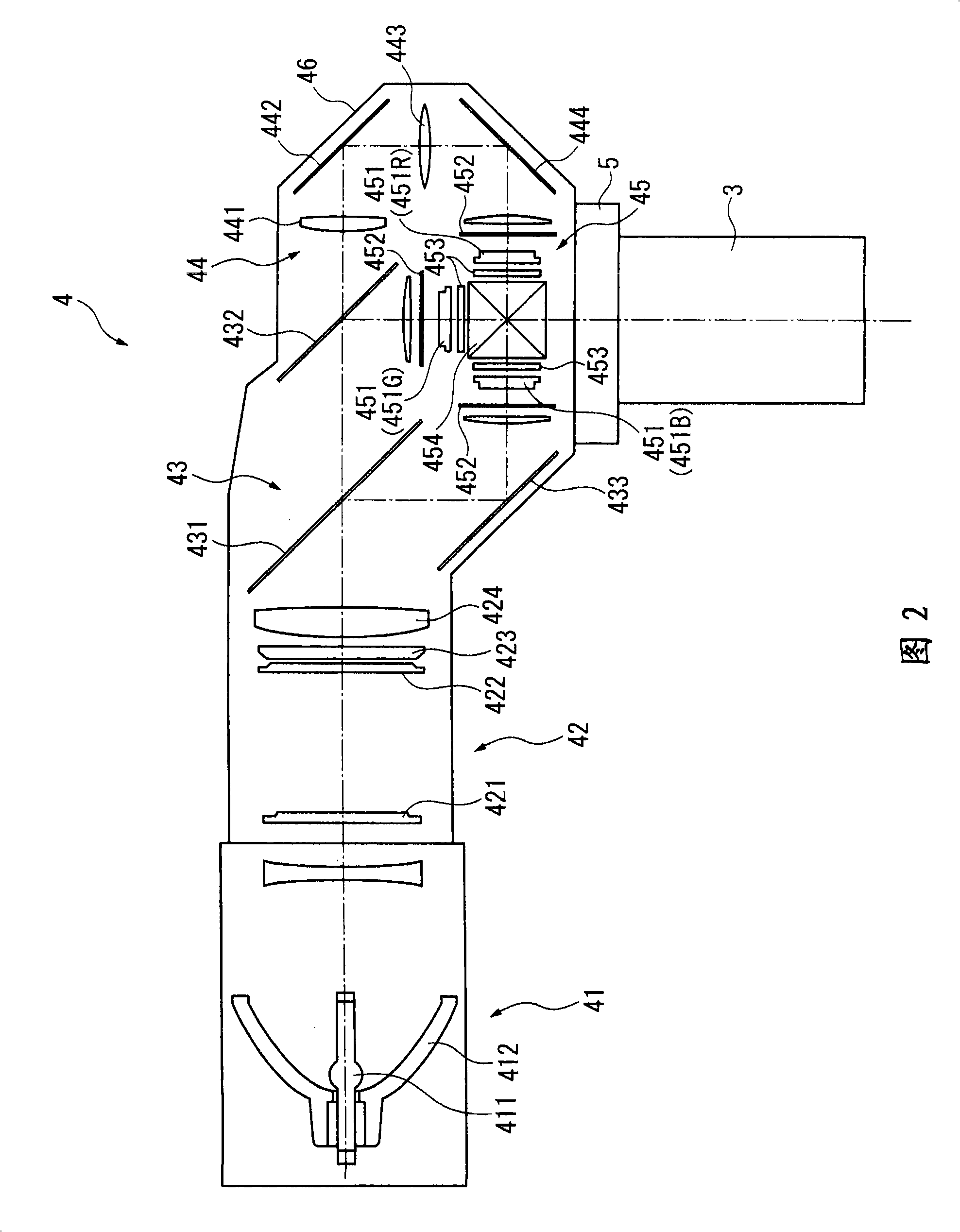
[0048] The projector 1 modulates a light beam emitted from a light source according to image information to form image light, and enlarges and projects the formed image light on a screen (not shown). As shown in FIG. 1 , the present projector 1 includes a package case 2 constituting a package.

[0049] The packaging case 2 accommodates the main b...


PUM


Abstract

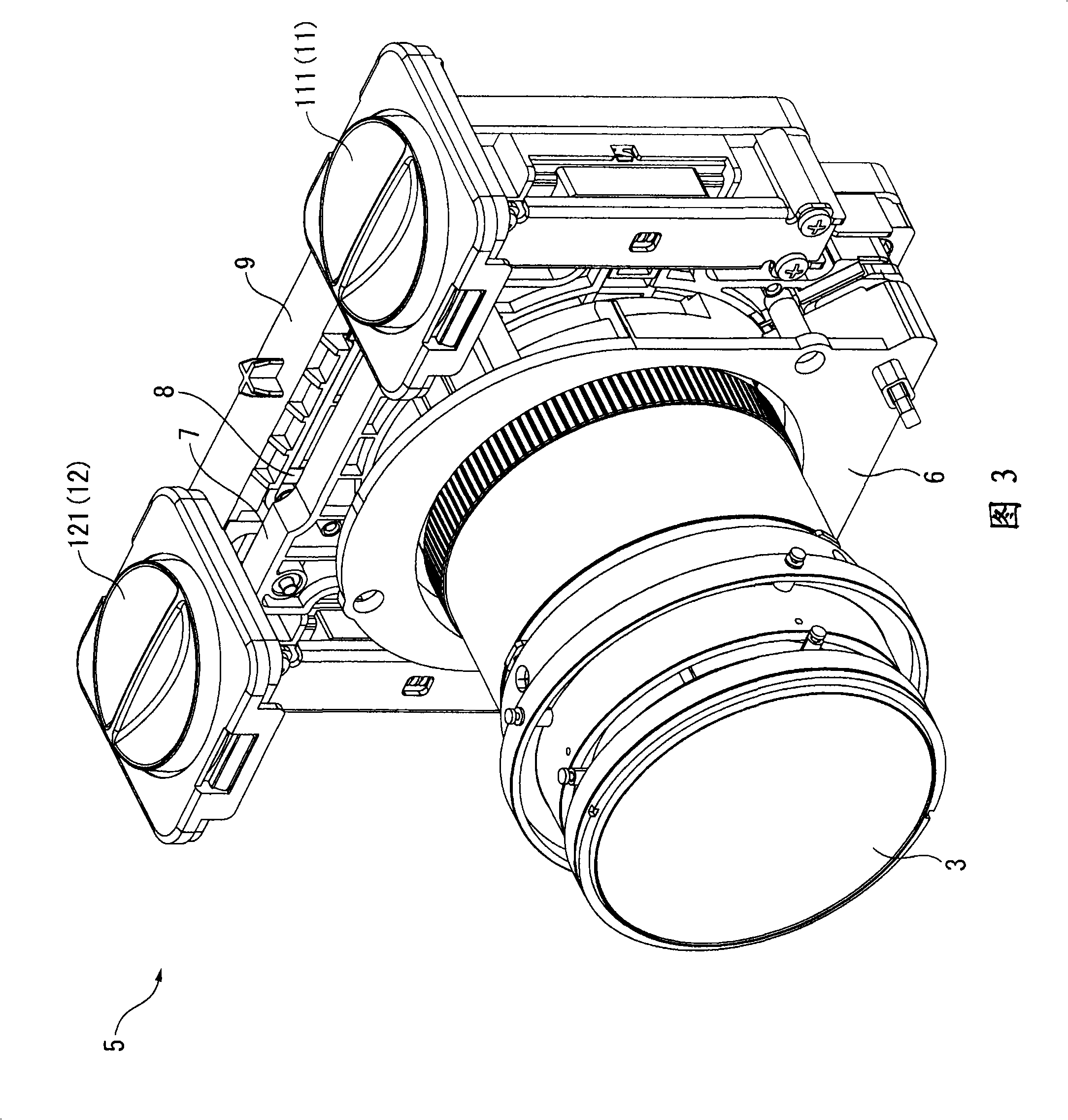
The present invention provides a projector, capable of stably maintaining the focusing accuracy of a projection image even though adjusting projection position, and implementing miniaturization and lightweighting. A projection position adjusting device (5) of the projector is provided with four interlinking members (13) for connecting a first moving plate (7) movably relative to a fixed member (9). The interlinking members (13) includes a connection member (136), which is a step shape with a step part (134) one end of which has a smaller section area relative to the other end, and the end is interlinked with the first moving plate (7) when the fixed member (9) is inserted in an insertion hole for interlink; and a interposition mounting member (137), arranged between the step part (134) and a step part (923A) of the insertion hole (923), loading in the direction of leaving each step part (134, 923A), so that the first moving plate (7) contacts with the fixed member (9).

Description

technical field [0001] The present invention relates to projectors. Background technique [0002] Conventionally, there is known a projector that modulates a light beam emitted from a light source according to image information, and enlarges and projects the light beam on a screen using a projection optical device. [0003] In such a projector, there are cases where the projector is fixed at a low position to project upwards, and fixed at a high position to project downwards. Furthermore, in addition to projecting in their vertical directions, they project in the horizontal direction. The case of projection. Therefore, it is known to provide a projection position adjustment device for moving the projection optical device in a direction perpendicular to the direction of the emitted light beam (projection direction) in an optical system such as a light modulation device (for example, refer to Patent Document 1). [0004] In the projection position adjusting device described ...

Claims


Application Information

Patent Timeline
Patent Type & Authority Applications(China)
IPC IPC(8): G03B5/00G03B21/14
CPCG03B27/62
Inventor 北原亘中村训久栗原彻
Owner SEIKO EPSON CORP
Why Eureka
Eureka Blog
Learn More