
Capillary membrane filtration module

A capillary and membrane technology, applied in the field of external pressure capillary membrane filters, can solve the problems of hindering the free passage and circulation of air and untreated water.

Inactive Publication Date: 2009-07-29
佛兰芒技术研究所
View PDF6 Cites 2 Cited by
  • Summary
  • Abstract
  • Description
  • Claims
  • Application Information

AI Technical Summary

Problems solved by technology

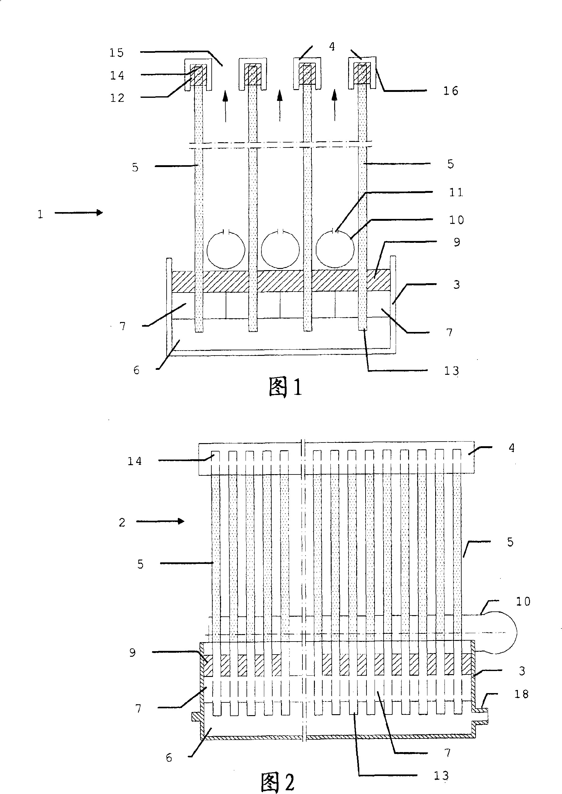
This configuration has the risk of trapping dust in the upper header which hinders the free passage and circulation of air and raw water at the top of the module

Method used

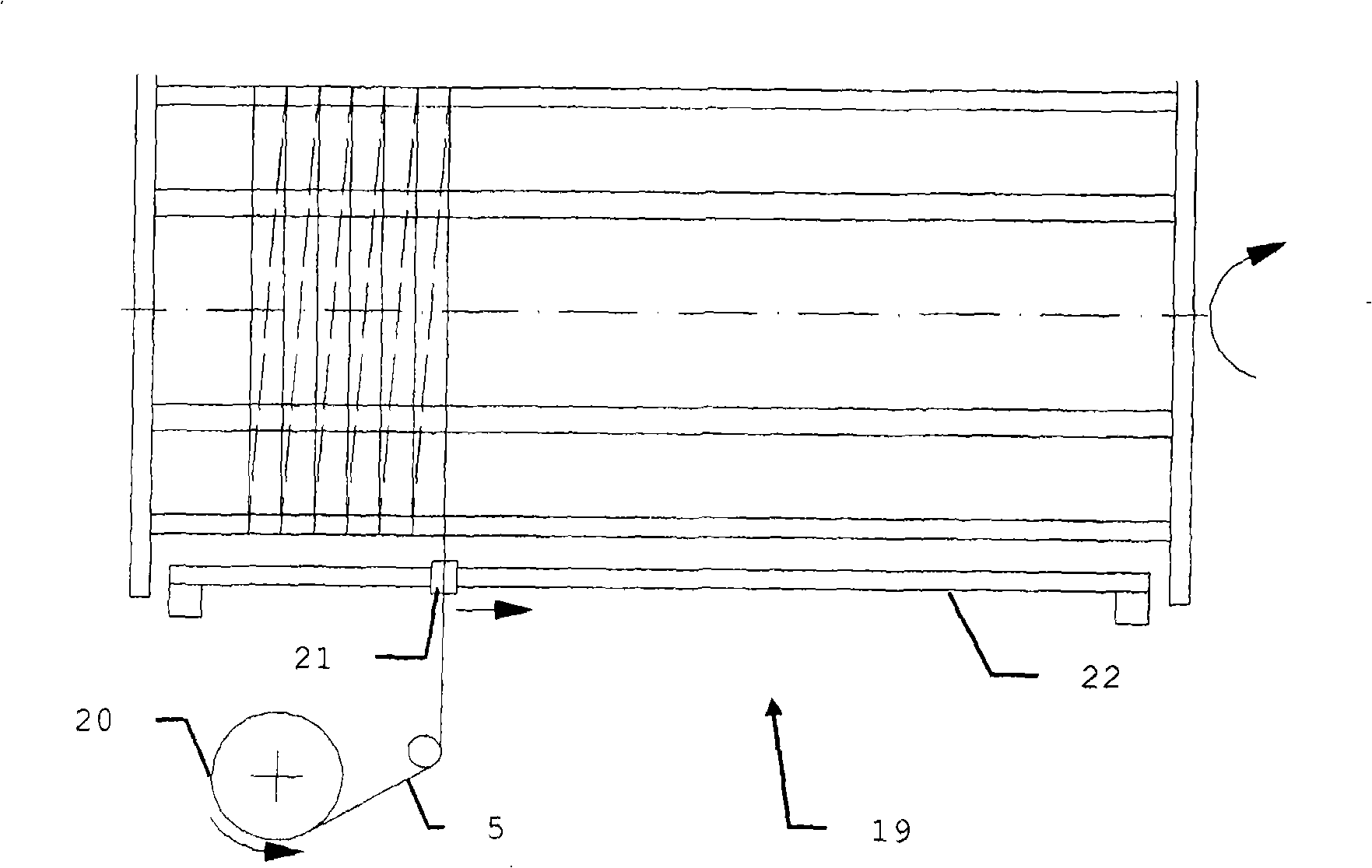
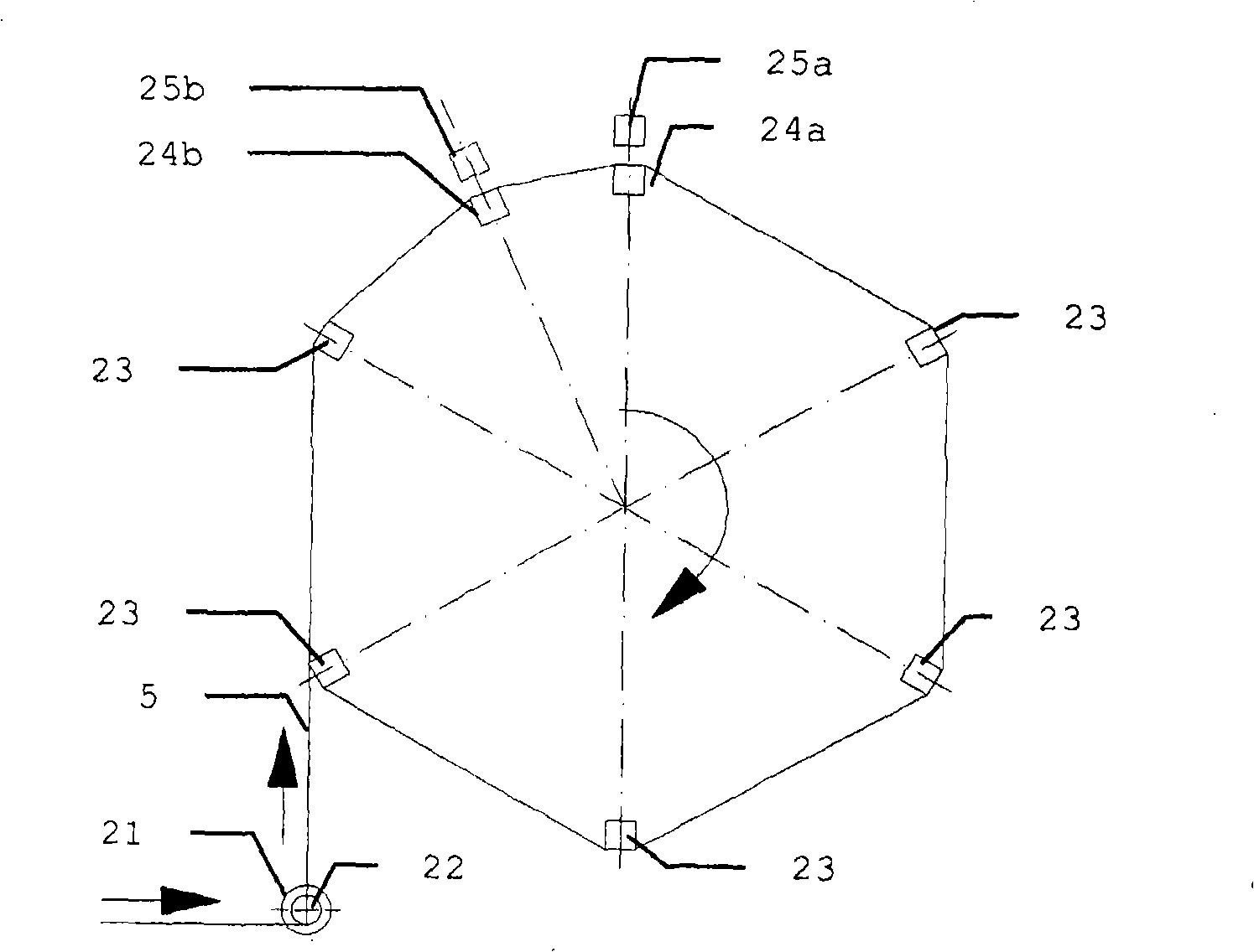

Image

  • Capillary membrane filtration module
  • Capillary membrane filtration module
  • Capillary membrane filtration module

Examples


Embodiment Construction

[0021] Capillary membranes suitable for use in the practice of the invention are disclosed in WO2006 / 053406. However, the present invention is not limited to the use of these particular capillary membranes.

[0022] The capillary membranes are suspended side by side to form planar vertical layers. Thus, the planar vertical layer comprises capillary membranes arranged in a single row. In the present invention, each single row of capillary membranes is regarded as a planar membrane assembly.

[0023] At one side (bottom side), several such planar layers are packaged together in a header parallel to each other. The membrane ends are left open here so that the permeate is collected and drained from all membrane layers together. At the other side (top side), each planar layer (each single row) of capillary membranes has a separate upper header. Here headers can also be used as collectors or can be closed at the ends. The gap maintained between two adjacent headers allows untre...


PUM


Abstract

The present invention is related to a filtration device for removing particles from a liquid. The filtration device comprises a collector header and a plurality of planar membrane assemblies having an upper side and a lower side, the lower side being operatively linked to the collector header. Each planar membrane assembly is formed as a single row of a plurality of capillary membranes and is linked to an individual upper header.

Description

technical field [0001] The present invention relates to an outside-in capillary membrane filter for water treatment. Background technique [0002] Filters for water treatment with capillary ultrafiltration or microfiltration membranes with minimum porosity at their outer diameter (so-called "external capillary membranes") pass through at the inner diameter ("lumen") side Apply lower pressure to filter untreated water. Permeate flows from the outer diameter towards the lumen, but dust collects at the outer perimeter and is removed by air scrubbing and / or post-pulse. This requires good contact between the air bubble and the capillary membrane. Other points involved are avoiding trapping of entrained dust and having a design that can be constructed in an economical manner. Different modules are designed to meet these proposed requirements. [0003] In US patent 5,248,424 a capillary membrane module is described consisting of a layer of membranes enclosed at both ends in a h...

Claims


Application Information

Patent Timeline
Patent Type & Authority Applications(China)
IPC IPC(8): B01D63/02B01D65/08C02F1/44
CPCC02F1/444B01D63/026B01D2321/185B01D63/024B01D63/021B01D65/08B01D2313/21B01D63/02B01D2323/42B01D63/033
Inventor H·贝克尔斯W·杜瓦扬
Owner 佛兰芒技术研究所
Learn More