Horizontal conveyance mechanism for self-propelled carriage

A transport mechanism and self-propelled technology, which is applied to elevated railway systems with suspended vehicles, railway systems with propulsion equipment, locomotives, etc., and can solve problems such as system enlargement, excessive curvature radius, and curvature radius increase

Active Publication Date: 2009-07-29
S & S ENG
View PDF1 Cites 9 Cited by
  • Summary
  • Abstract
  • Description
  • Claims
  • Application Information

AI Technical Summary

Problems solved by technology

However, it is known that when there is a heavy load on one side in a container suspended by a gyroscopic device, it is difficult to maintain a horizontal attitude due to the container tilting under the action of the unbalanced load
[0006] In addition, since a gyro device is used to always maintain the horizontal attitude of the container and the vehicle frame travels by turning (turning) from the horizontal track to the vertical track, the tu

Method used


Image

  • Horizontal conveyance mechanism for self-propelled carriage
  • Horizontal conveyance mechanism for self-propelled carriage
  • Horizontal conveyance mechanism for self-propelled carriage

Examples


Embodiment Construction

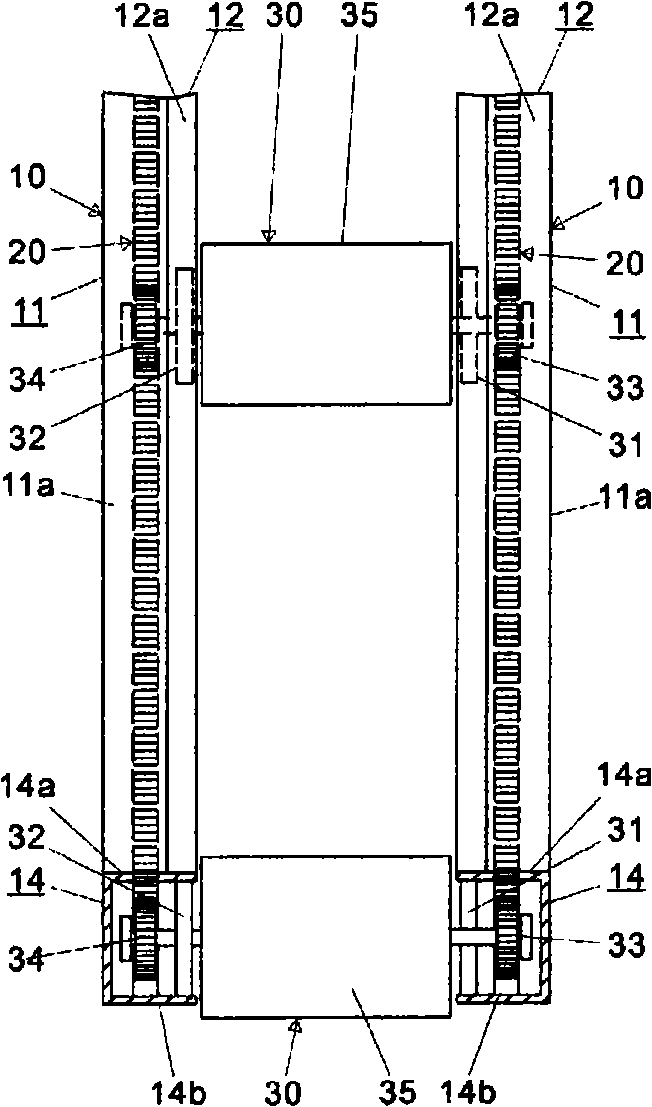
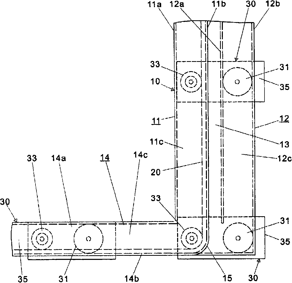
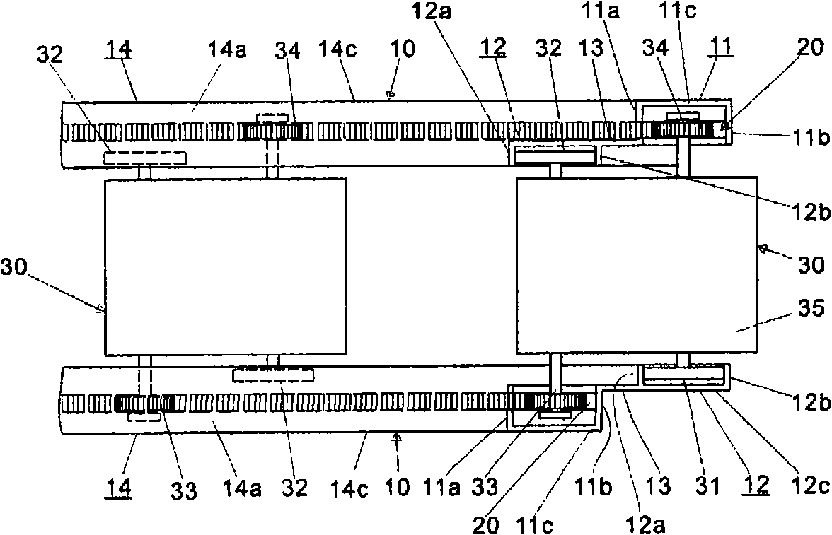
[0024] The embodiment of the horizontal conveying mechanism of the self-propelled vehicle frame of the present invention will be described below with reference to the accompanying drawings. In the attached picture, figure 1 It is a front view showing an embodiment of the horizontal transport mechanism of the self-propelled vehicle frame according to the first structure of the present invention, figure 2 yes figure 1 Right side view of the horizontal transport mechanism shown, image 3 yes figure 2 top view of Figure 4 yes Figures 1 to 3 A perspective view of the horizontal transport mechanism of the first structure shown, Figure 5 It is a front view showing an embodiment of the horizontal transport mechanism of the self-propelled vehicle frame according to the second structure of the present invention, Figure 6 yes Figure 5 Right side view of the horizontal transport mechanism shown, Figure 7 yes Figure 6 top view of Figure 8 yes Figures 5 to 7 A perspect...


PUM


Abstract

A conveyance mechanism having rails (10) horizontally and vertically laid in a building, racks (20) laid along the rails, wheels (31, 32) for traveling on the rail, and a self-propelled carriage (30) having pinions (33, 34) meshing with the racks and a drive section for the pinions and on which a load is placed. The rails have a curve section in which they change the direction from horizontal to vertical or from vertical to horizontal, and also have a vertical section continuing to the horizontal section. In the two sections above, the rails have rails (11) for the pinions, having the racks meshing with the pinions, and also have rails (12) for the travel wheels, installed in parallel with and separated from the rails for the pinions. The carriage have, on its left and right sides, the pinions meshing with the rails for the pinions and the travel wheels supported on the rails for the travel wheels. Also, the rails for the pinions and the rails for the travel wheels are arranged so that the carriage can move in a horizontal position in the curve section and the vertical section continuing to the curve section.

Description

technical field [0001] The present invention relates to a horizontal conveying mechanism for making a self-propelled vehicle frame always travel in a horizontal posture in a conveying system for moving a conveying body composed of a container and a vehicle frame along a plurality of floors of a building or the like. Tracks laid horizontally on the floor and along tracks laid vertically (vertically) on the walls, and loads are unloaded from containers to stations arranged along the tracks and loaded from the stations to the containers input loads such as documents, parts, etc. Background technique [0002] This type of delivery system is widely used because they can automatically transport documents, mail, stationery, etc. in offices, medical records in hospitals, parts and products in factories, and deliver items such as samples, Reagents and other loads. [0003] This transportation system is constituted by rails laid horizontally and vertically in a building, carriages t...

Claims


Application Information

Patent Timeline
IPC IPC(8): B61B13/04B61B3/02B61B13/12
CPCB61B13/02B61B15/00B61C11/04
Inventor 铃木裕司鹤森宪一郎增嶌稔
Owner S & S ENG
Why Eureka
Try Eureka