Device for detecting the three states of a circuit breaker

A technology of three states and detection devices, applied in emergency protection devices, switchgear status indicators, circuits, etc., can solve the problems of insufficient electrical connection of movable contacts, affecting the quality of electrical connections, and gradual wear and tear.

Inactive Publication Date: 2009-07-29
SCHNEIDER ELECTRIC IND SAS
View PDF3 Cites 1 Cited by
  • Summary
  • Abstract
  • Description
  • Claims
  • Application Information

AI Technical Summary

Problems solved by technology

These rails may gradually wear out as the driving components switch on and off, ultimately affecting the quality of the electrical connection
Also, if the drive part has some play in one of its positions, the electrical connection between the movable contact and the corresponding magnetic track may be insufficient

Method used


Image

  • Device for detecting the three states of a circuit breaker
  • Device for detecting the three states of a circuit breaker
  • Device for detecting the three states of a circuit breaker

Examples


Embodiment Construction

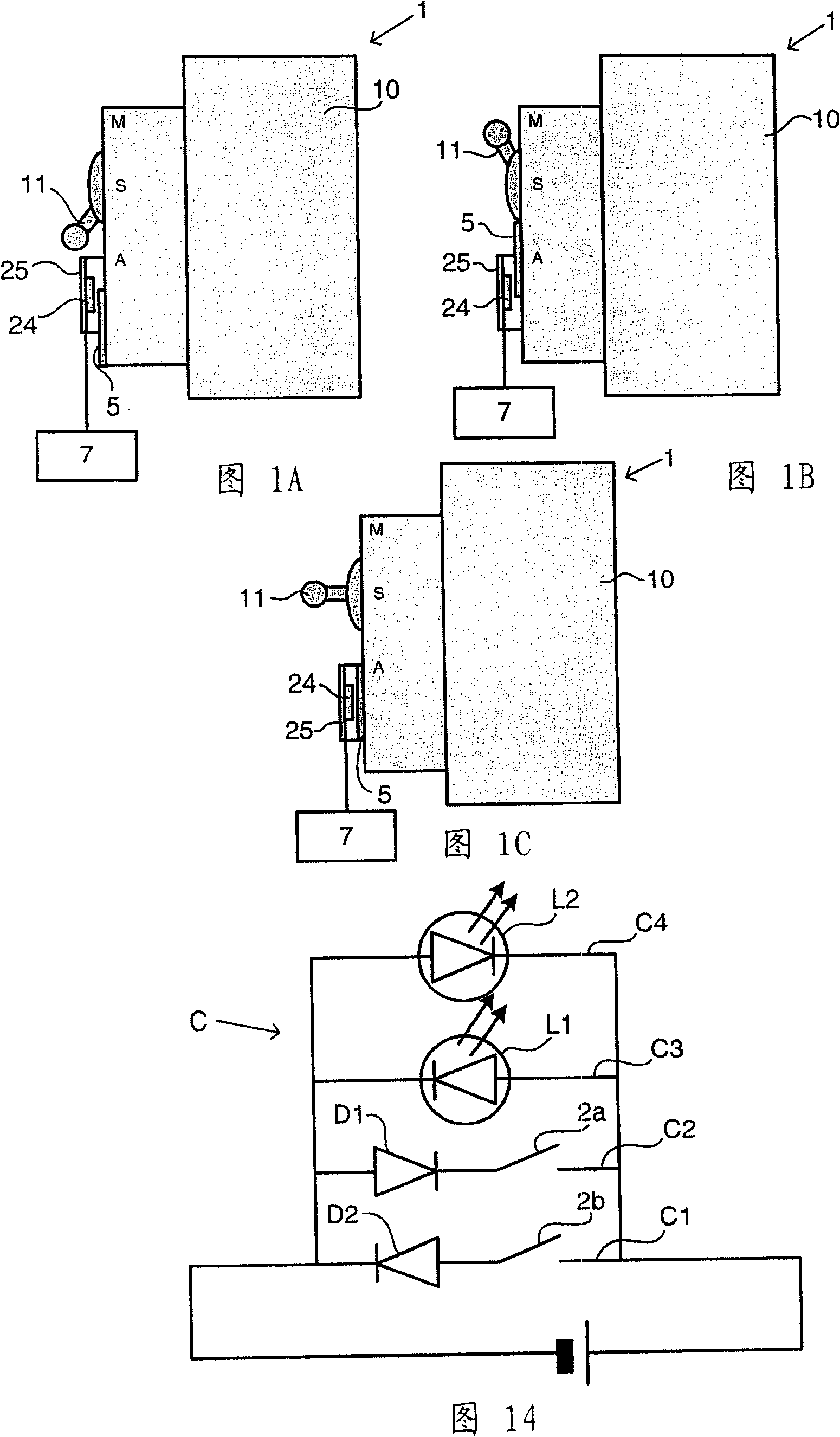
[0032] The detection device of the present invention is designed to be installed in a three-position circuit breaker 1 . In a known manner, the circuit breaker 1 comprises a housing 10 on which is mounted a drive member constituted by an operating device 11 , for example pivoted or rotated. In Figures 1A to 1C the operating means has the shape of a pivot lever, but it should be understood that it could equally well be in the shape of a rotary button.

[0033] The operating device 11 can move between three positions: the "on" (M) position, the "off" (A) position and the intermediate position between the "on" (M) position and the "off" (A) position. "Trip" (D) position. When an electrical fault (such as a short circuit) is detected, the operating device automatically moves from the "on" (M) position to the "trip" (D) position. In each of the three positions (M, A, D) of the operating device 11, the circuit breaker is respectively in the "ON", "OFF" or "TRIP" position respectiv...


PUM


Abstract

The present invention concerns a device for detecting three states, namely 'on', 'off' and 'triggered' of an electric circuit breaker (1), comprising a mobile magnetic device (40, 41), movable between three positions corresponding to the three states of the circuit breaker (1) and comprising at least one permanent magnet (400, 401, 410) generating a magnetic field provided with magnetic field lines (L) for driving two DIP switches (2a, 2b) via the magnetic effect. In each of the magnetic device's positions (40, 41), the two DIP switches are controlled in either an open or closed position to form a specific combination representing one of the three states of the circuit breaker (1).

Description

technical field [0001] The invention relates to a device for detecting three states of "on", "off" and "tripping" of a circuit breaker. Background technique [0002] A device for detecting and signaling the "on", "off" and "trip" states of a circuit breaker is known from document US 4,969,063. The device includes a three-position switch mechanically connected to a component for actuating the circuit breaker. A three-position switch is realized by means of three electrical rails, each of which is assigned to a position of the drive part and interacts with a movable electrical contact fixed to the drive part. Depending on the position of the driving part, the switch turns on a first LED of a first color, a second LED of a second color, or both LEDs simultaneously to mix their colors. [0003] This device works by mechanical contact between the drive part and the electrical rail. These rails may gradually wear out as the driving components switch on and off, ultimately affec...

Claims


Application Information

Patent Timeline
Patent Type & Authority Applications(China)
IPC IPC(8): H01H71/04H01H36/00
CPCH01H2050/007H01H2071/042H01H2036/0093H01H47/002H01H2071/048H01H71/04
Inventor 劳伦特·奇希斯蒂法妮·科洛特贝努瓦·格拉普西尔万·佩尼厄马克·沃内
Owner SCHNEIDER ELECTRIC IND SAS
Why Eureka
Try Eureka