LED device

A technology of light-emitting diodes and light-emitting chips, which is applied in the direction of semiconductor devices, electrical components, circuits, etc., can solve the problems of unseen technology development, no prevention, and reduced efficiency of phosphor powder, so as to increase the sorting range, be less prone to heat, and improve the mixing efficiency. light effect effect

Active Publication Date: 2009-08-05
AU OPTRONICS CORP
View PDF0 Cites 9 Cited by
  • Summary
  • Abstract
  • Description
  • Claims
  • Application Information

AI Technical Summary

Problems solved by technology

[0006] To sum up, the light-emitting chip array assembled after sorting can ensure the quality of light emission, but the cost is high, which is not in line with economic benefits
Phosphor powder is affected by temperature and the efficiency is reduced, however, there is still no way to prevent it in the design of the prior art
Furthermore, when the light-emitting chip array is used in the backlight module, it needs to have different light-emitting angles in different directions, and there is no corresponding technology development in the existing technology.

Method used


Image

  • LED device
  • LED device
  • LED device

Examples


Embodiment Construction

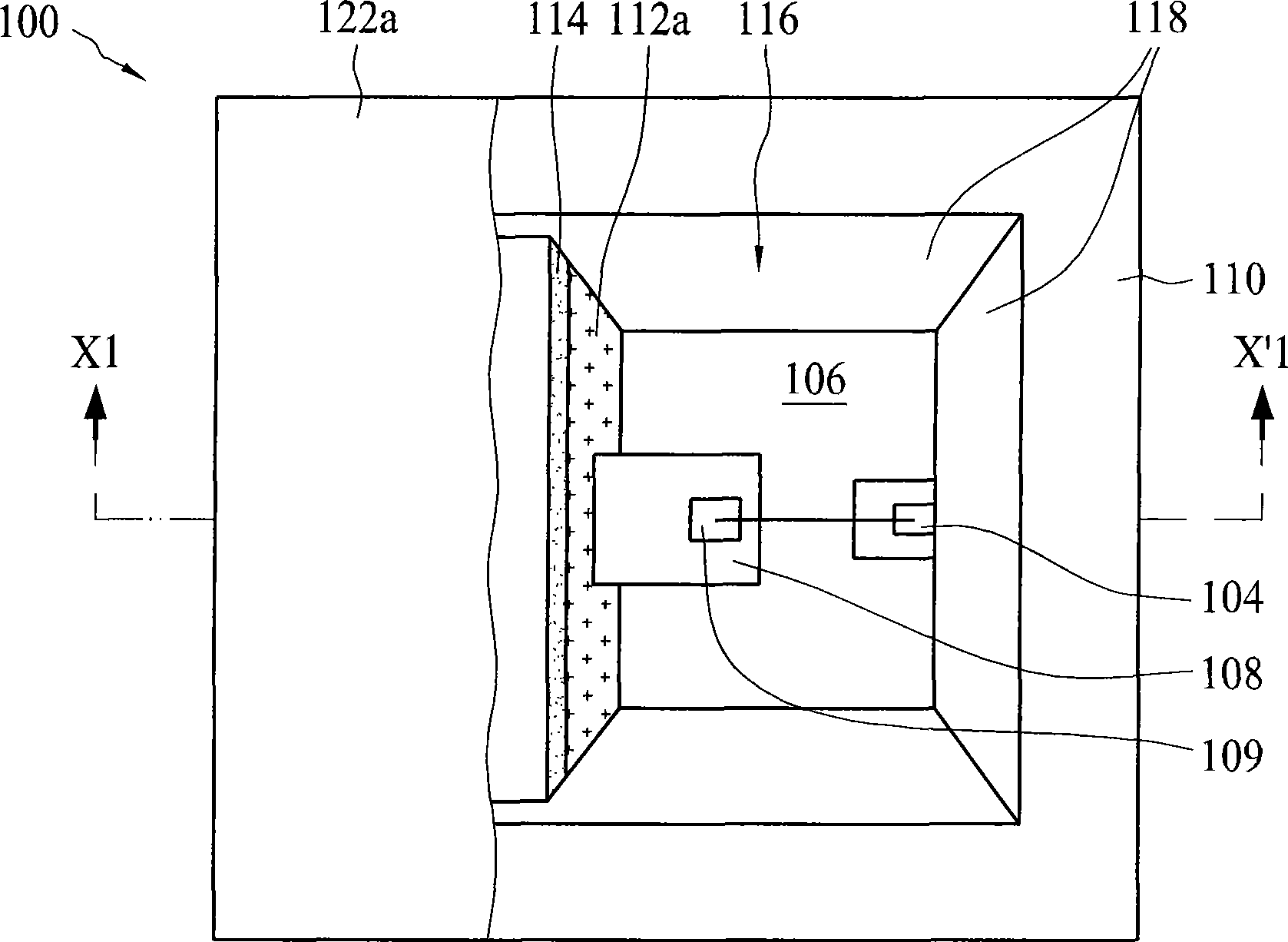
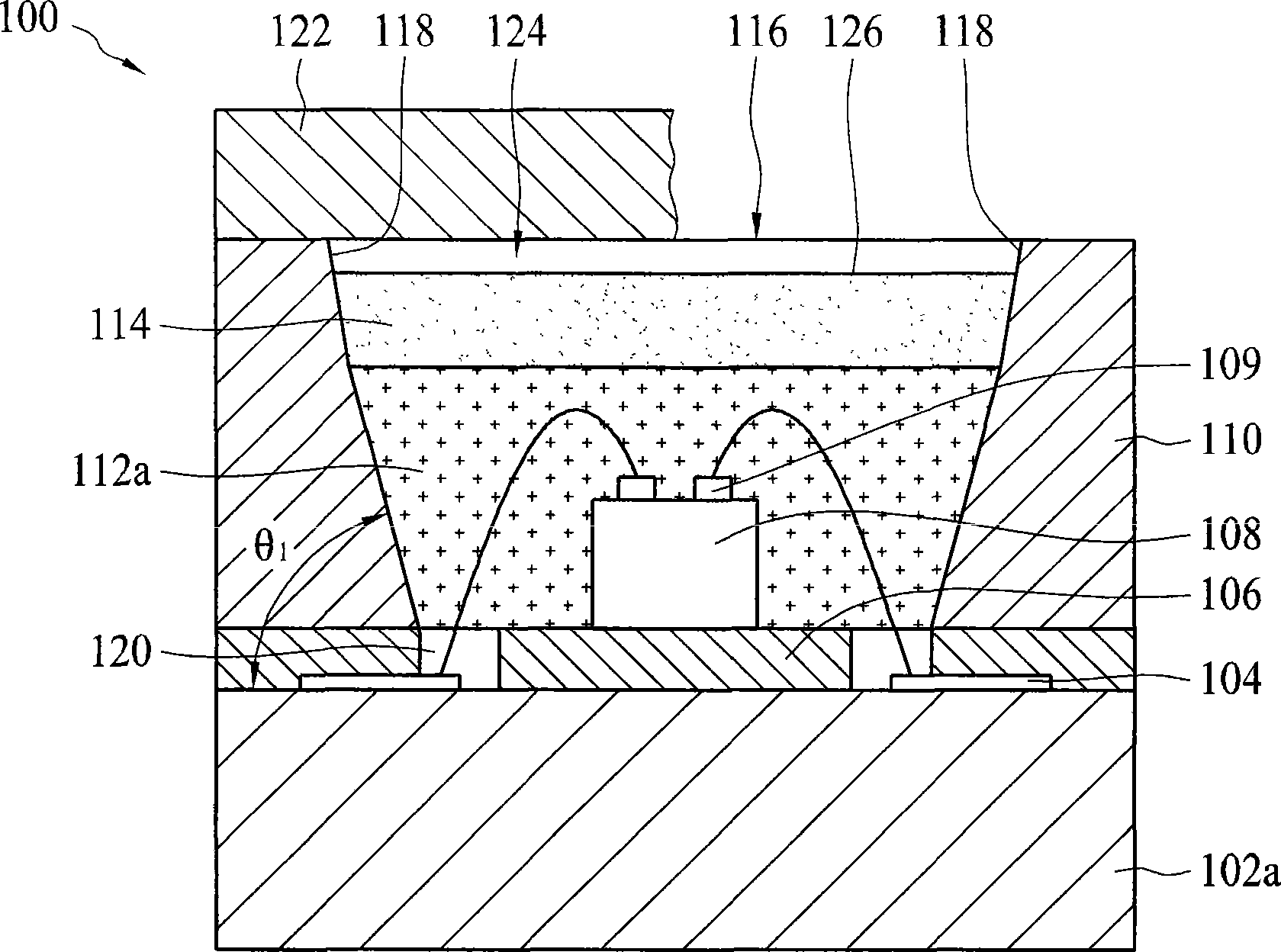
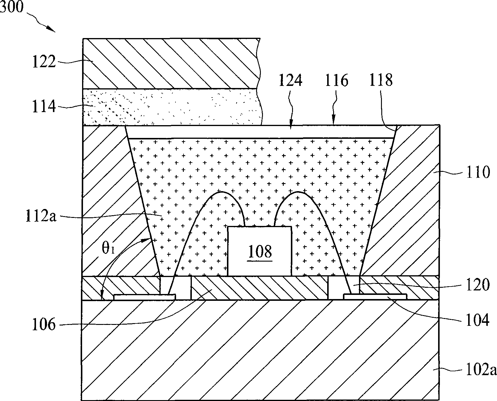
[0044] figure 1 A top view of the LED device 100 according to the first embodiment of the present invention is shown. figure 2 for figure 1 Sectional view along section line X1-X’1. The LED device 100 includes a substrate 102a with a circuit pattern 104, a reflective layer 106 disposed on the substrate 102a, at least one light-emitting chip 108 disposed on the reflective layer 106, and a reflector 110 surrounding the light-emitting chip 108. , a colloid 112a covering the light-emitting chip 108 and a phosphor layer 114 disposed on the colloid 112a for uniform light mixing. The light-emitting chip 108 has a conductive portion 109 , and the circuit pattern 104 of the substrate 102 a is connected to the conductive portion so as to provide driving power for the light-emitting chip 108 .

[0045] The reflector 110 includes a light emitting surface 116 at the outlet of the reflector and a first reflective surface 118 at the inner edge of the reflector. The first reflective surf...


PUM


Abstract

The invention discloses a light-emitting diode device which includes a substrate with a circuit pattern, a reflective layer arranged on the substrate, at least one light-emitting chip arranged on the reflective layer, a reflector winding the light-emitting chip, a colloid covered on the light-emitting chip, and a phosphor powder layer arranged above the colloid. The light-emitting chip has a conductive part, and the circuit pattern of the substrate is connected with the conductive part. In the embodiment, a plurality of light-emitting chips are arranged in a linear way, moreover, a distance piece is arranged between two adjacent light-emitting chips.

Description

technical field [0001] The invention relates to a light-emitting diode device, in particular to a light-emitting diode device which expands the sorting range of light-emitting chips by improving the light mixing effect. Background technique [0002] Due to various variations in the manufacture of light-emitting chips, there will be some differences in characteristics such as brightness or light-emitting wavelength between the manufactured light-emitting chips. At the beginning of using light-emitting chips as lighting, most of them are single-chip users, and the control requirements for brightness or color are not high, so the difference between light-emitting chips is not obvious. [0003] However, when a plurality of light-emitting chips are arranged in an array for use, if there is no sorting process, the overall brightness or color may be uneven. In order to solve this problem, the light-emitting chips are classified according to some characteristic parameters, and afte...

Claims


Application Information

Patent Timeline
Patent Type & Authority Applications(China)
IPC IPC(8): H01L25/075H01L33/00
CPCH01L2224/48091H01L2924/181H01L2924/1815
Inventor 洪春长邵栋梁林正中
Owner AU OPTRONICS CORP
Why Eureka
Try Eureka