Gas cylinder link mechanism used for piston type internal combustion engine or gas compressor

A technology of internal combustion engine and gas compressor, which is applied in the field of cylinder connecting rod mechanism to achieve the effects of increasing movement speed, eliminating slap and improving lubrication state

Inactive Publication Date: 2009-08-12
唐人忠
View PDF0 Cites 11 Cited by
  • Summary
  • Abstract
  • Description
  • Claims
  • Application Information

AI Technical Summary

Problems solved by technology

[0003] The purpose of the present invention is to solve the problem of side pressure and slapping between the piston and the cylinder due to the use of the crank connecting rod mechanism in the existing piston internal combustion engine or gas compressor, and to provide a piston internal combustion engine or gas compressor. Cylinder linkage on compressor

Method used


Image

  • Gas cylinder link mechanism used for piston type internal combustion engine or gas compressor
  • Gas cylinder link mechanism used for piston type internal combustion engine or gas compressor
  • Gas cylinder link mechanism used for piston type internal combustion engine or gas compressor

Examples


specific Embodiment approach 1

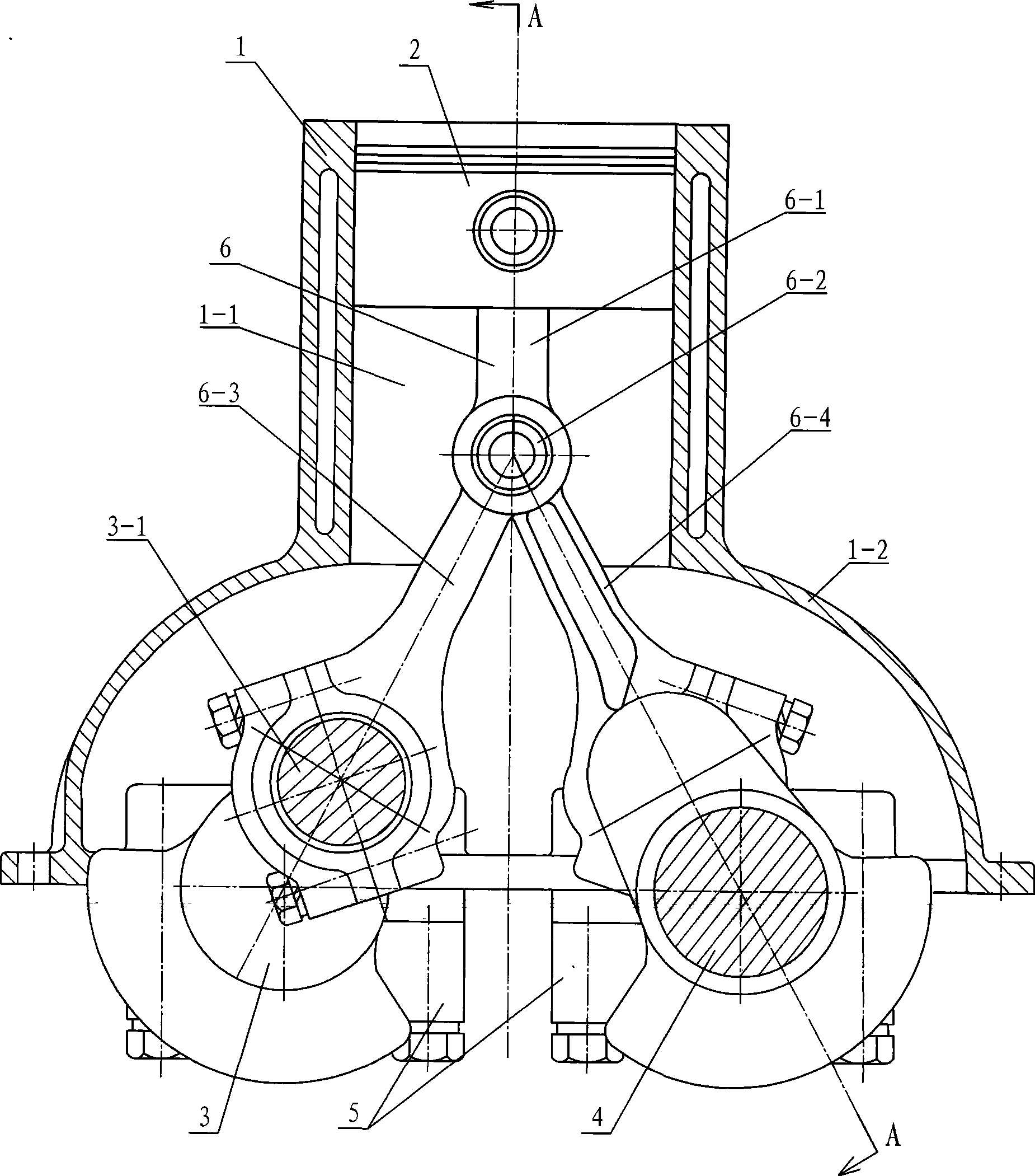
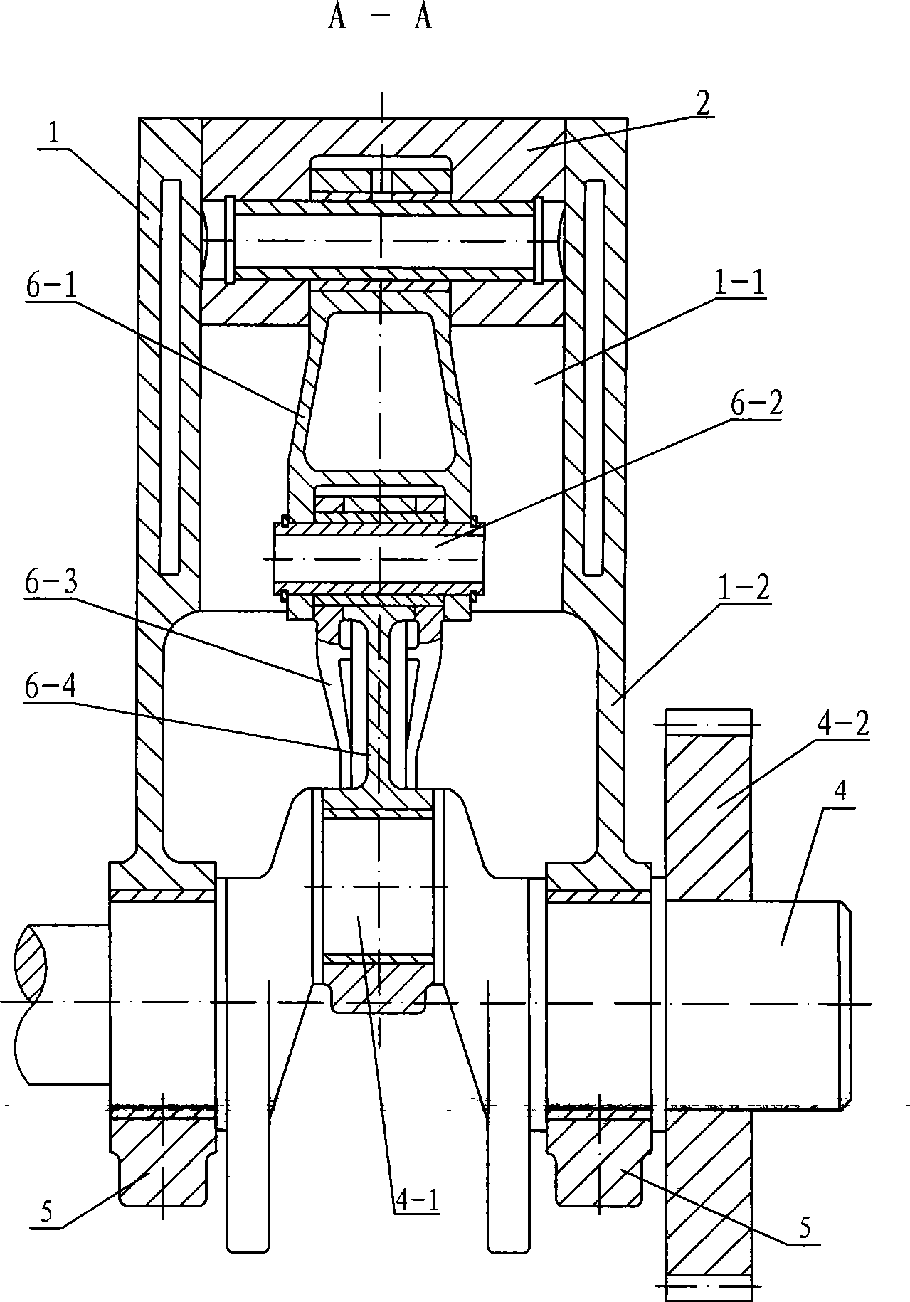
[0010] Specific implementation mode one: combine figure 1 , figure 2 and Figure 7Describe this embodiment, this embodiment includes a first cylinder block 1, at least one piston 2, a first crankshaft 3, a second crankshaft 4, a first gear 3-2, a second gear 4-2, a plurality of bearing housings 5 ​​and At least one first primary and secondary linkage mechanism 6, the first cylinder block 1 is composed of at least one cylinder 1-1 and at least one first crankcase 1-2, the cylinder 1-1 is located in the first crankcase 1-2 The top and the two are integrated, the cylinder 1-1 communicates with the inner cavity of the first crankcase 1-2, the piston 2 is installed in the cylinder 1-1, the first crankshaft 3 and the second crankshaft 4 are along the first crankcase The width direction of the body 1-2 is set in the inner chamber of the first crankcase 1-2 and installed on the bottom of the first crankcase 1-2 through the bearing seat 5, and the second gear 4-2 is fixed on the se...

specific Embodiment approach 2

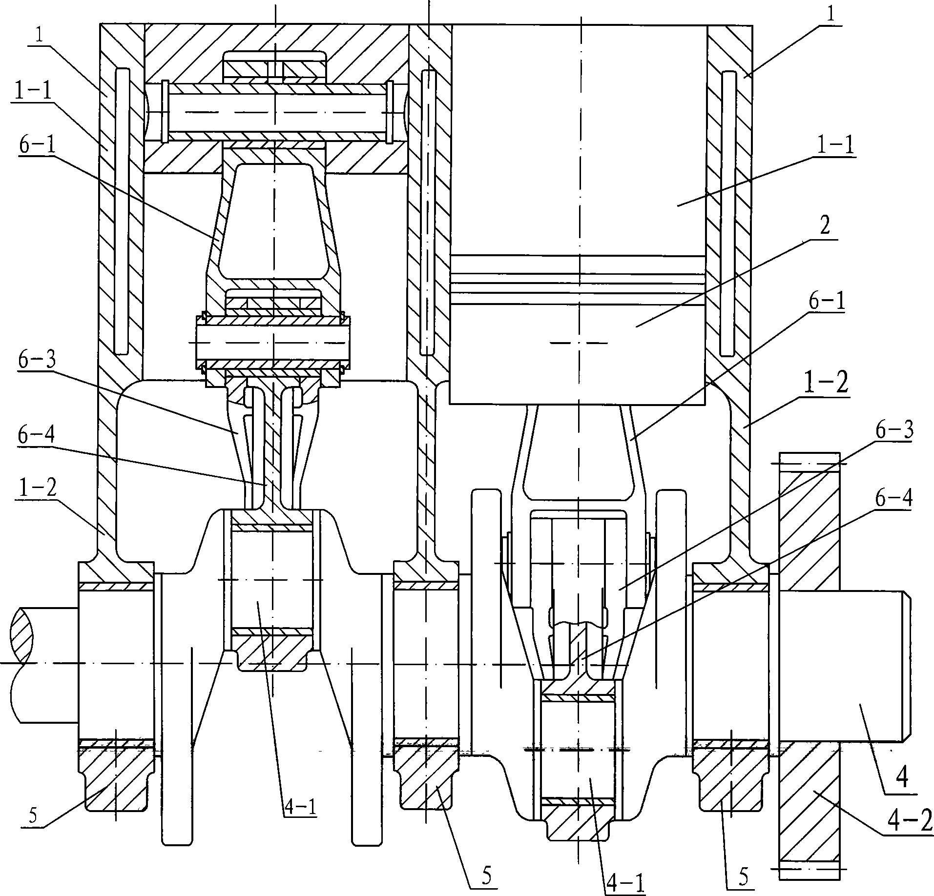
[0011] Specific implementation mode two: combination image 3 and Figure 8 Describe this embodiment, there are two cylinders 1-1 and first crankshaft housings 1-2 in this embodiment, two cylinders 1-1 and two first crankshaft housings 1-2 along the first crankshaft 3 and The axial direction of the second crankshaft 4 is arranged side by side, the first crankshaft 3 is provided with two first crankpins 3-1, the second crankshaft 4 is provided with two second crankpins 4-1, each cylinder 1-1 A piston 2 is housed inside, and each piston 2 is hinged with a set of first primary and secondary linkage mechanisms 6, and so on, the first cylinder block 1 can be provided with three crankshafts along the axial direction of the first crankshaft 3 and the second crankshaft 4 Above the first cylinder 1-1.

[0012] The working process of the specific embodiment one and the specific embodiment two:

[0013] see figure 1 , for an internal combustion engine, during the explosive stroke, t...

specific Embodiment approach 3

[0014] Specific implementation mode three: combination Figure 4 , Figure 5 and Figure 7 Describe this embodiment, this embodiment includes a first cylinder block 1, at least one piston 2, a first crankshaft 3, a second crankshaft 4, a first gear 3-2, a second gear 4-2, a plurality of bearing housings 5 ​​and At least one second main and auxiliary connecting rod mechanism 16, the first cylinder block 1 is composed of at least one cylinder 1-1 and at least one first crankcase 1-2, and the cylinder 1-1 is located in the first crankcase 1-2 The top and the two are integrated, the cylinder 1-1 communicates with the inner cavity of the first crankcase 1-2, the piston 2 is installed in the cylinder 1-1, the first crankshaft 3 and the second crankshaft 4 are along the first crankcase The width direction of the body 1-2 is set in the inner chamber of the first crankcase 1-2 and installed on the bottom of the first crankcase 1-2 through the bearing seat 5, and the second gear 4-2 i...


PUM


Abstract

The invention discloses a cylinder link mechanism for a piston type internal-combustion engine or on an air compressor, relates to a cylinder link mechanism, and solves the problem that lateral pressure and beat are generated between a piston and a cylinder in the prior piston type internal-combustion engine or the air compressor. In a first proposal, a single cylinder is adopted, and two secondary link levers have different structures and are hinged with a primary link lever through a link lever pin. A second proposal and the first proposal have the difference that the two secondary link levers have the same structure and are hinged with the primary link lever through two link lever pins. A third proposal and the first proposal have the difference that two cylinders are parallel, and two secondary link levers in each set of link mechanism have different structures and are hinged with the primary link lever through a link lever pin. A fourth proposal and the third proposal have the difference that the two secondary link levers in each set of link mechanism have the same structure and are hinged with the primary link lever through two link lever pins. A transmission mode of the primary-secondary link mechanism is adopted between the piston and a crank shaft, so that the lateral pressure is not generated between the piston and the cylinder, and the beat phenomenon between the piston and the cylinder is eliminated.

Description

technical field [0001] The invention relates to a cylinder linkage mechanism. Background technique [0002] At present, the known piston internal combustion engine or gas compressor adopts a crank connecting rod mechanism, and this connection makes the piston internal combustion engine or gas compressor generate a large side pressure F between the piston and the cylinder during operation. N , see the principle of mechanism Figure 17 , this side pressure F N In addition to deforming the piston, it also causes a large frictional resistance between the piston and the cylinder, and the friction loss work is very large. For example, for an internal combustion engine, the friction loss work between the piston and the cylinder accounts for about Friction loses about 50% of the work. In addition, the crank-link mechanism in this mechanism causes the phenomenon of "slapping" (also known as "knocking cylinder") between the piston and the cylinder. Contents of the invention [00...

Claims


Application Information

Patent Timeline
Patent Type & Authority Applications(China)
IPC IPC(8): F01B9/02F02B75/32F04B35/01
CPCF02B75/065
Inventor 唐人忠
Owner 唐人忠
Why Eureka
Try Eureka