
Main pipe type micro turbine group of dual-air compressor

A technology of compressors and gas turbines, which is applied in the direction of gas turbine devices, combustion air/combustion-air treatment, machines/engines, etc. It can solve the high-level problems of micro gas turbine units, and achieve the effects of improving operating performance, saving fuel, and high operating efficiency

Inactive Publication Date: 2009-08-12
HARBIN INST OF TECH
View PDF0 Cites 10 Cited by
  • Summary
  • Abstract
  • Description
  • Claims
  • Application Information

AI Technical Summary

Problems solved by technology

[0003] In order to solve the problem that the existing micro gas turbine unit cannot maintain a high operating efficiency within a wide range of load changes, the present invention further provides a dual compressor main pipe micro gas turbine unit

Method used


Image

  • Main pipe type micro turbine group of dual-air compressor
  • Main pipe type micro turbine group of dual-air compressor
  • Main pipe type micro turbine group of dual-air compressor

Examples


specific Embodiment approach 1

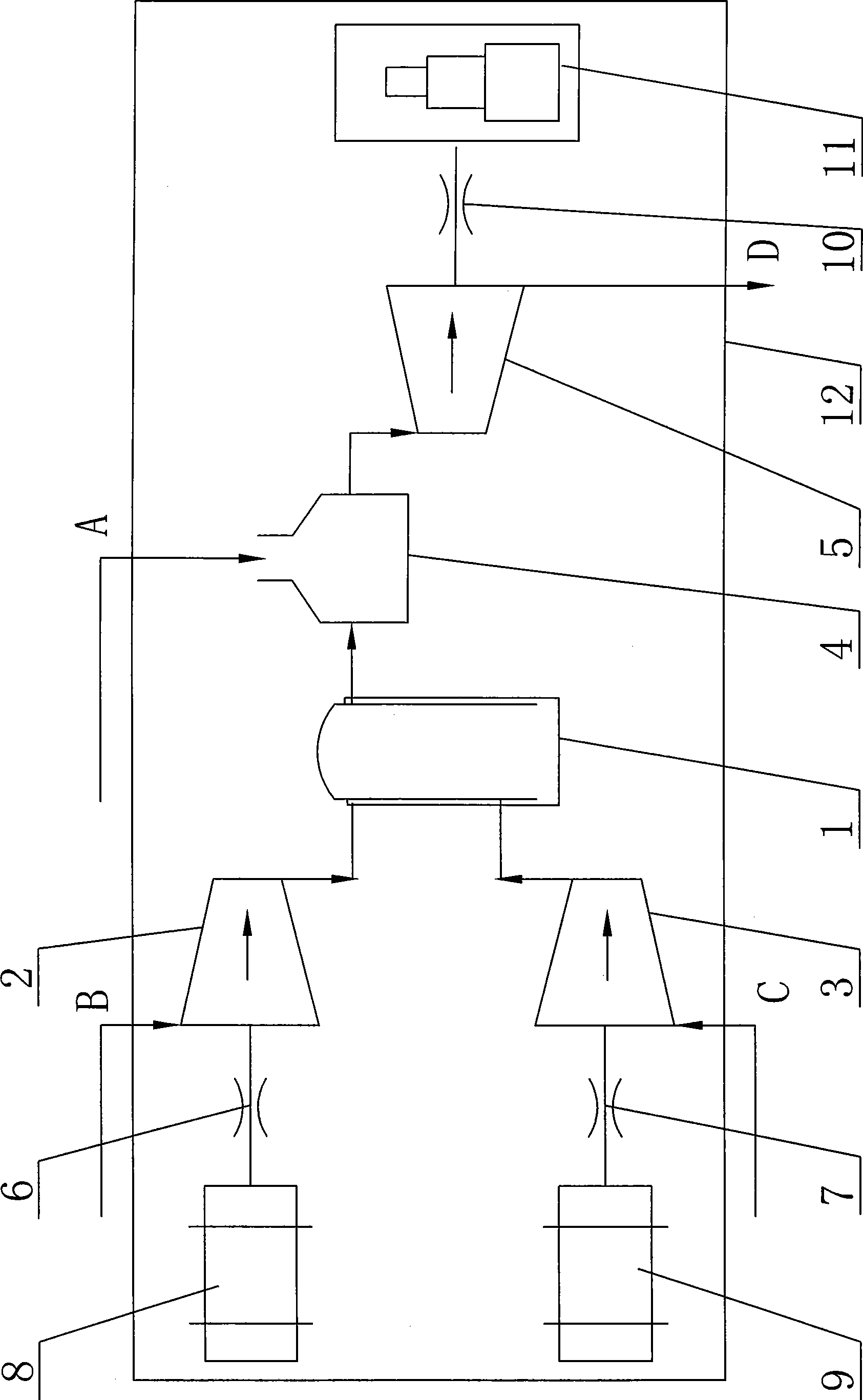
[0008] Specific implementation mode one: as figure 1 As shown, the dual-compressor main pipe type micro gas turbine unit described in this embodiment includes a main engine room 12, a combustion chamber 4, a turbine 5 and a third laminated coupling 10, and the micro gas turbine unit also includes a first electric motor 8. The second motor 9, the first lamination coupling 6, the second lamination coupling 7, the first compressor 2, the second compressor 3 and the main pipe 1; the combustion chamber 4, the turbine 5 , the third disc coupling 10, the first motor 8, the second motor 9, the first disc coupling 6, the second disc coupling 7, the first compressor 2 and the second compressor 3 and The main pipes 1 are all arranged in the main engine compartment 12; the output shaft of the first motor 8 is connected with the input shaft of the first compressor 2 through the first lamination coupling 6, and the output shaft of the second motor 9 is connected through the second laminati...

specific Embodiment approach 2

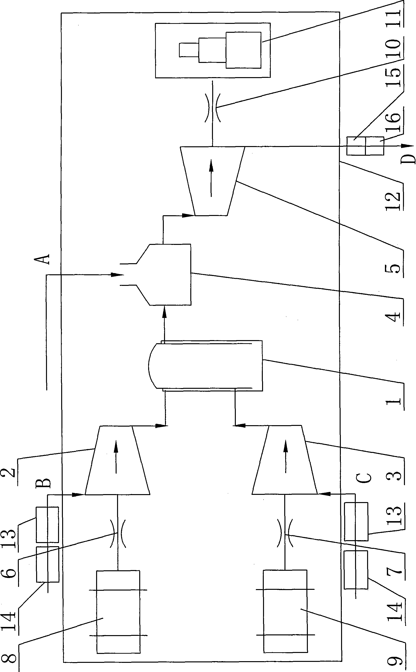
[0010] Specific implementation mode two: as figure 2 As shown, the micro gas turbine unit in this embodiment also includes two filter noise reduction devices 13 and two cabin ventilation intake noise reduction devices 14. End C is respectively provided with a filter noise reduction device 13 and a cabin ventilation intake noise reduction device 14 , and the two filter noise reduction devices 13 and two cabin ventilation intake noise reduction devices 14 are both arranged outside the main cabin 12 . Filtration noise reduction device 13 and cabin ventilation intake noise reduction device 14 are all prior art. Setting the filtering and muffler device 13 can effectively reduce and shield the noise generated by the present invention during operation, so that the noise around the unit can be effectively controlled and noise pollution can be reduced. The cabin ventilation intake muffler 14 is set so that the cabin temperature is slightly higher than the ambient temperature when the...

specific Embodiment approach 3

[0011] Specific implementation mode three: as figure 2 As shown, the micro gas turbine set in this embodiment also includes an exhaust introduction section 15 and an exhaust muffler device 16, and the exhaust introduction section 15 and the exhaust muffler device 16 are sequentially arranged at the exhaust outlet of the turbine 5. D, and the exhaust introduction section 15 and the exhaust muffler 16 are both arranged outside the main cabin 12 . Both the exhaust introduction section 15 and the exhaust muffler 16 are prior art. Exhaust introduction section-exhaust muffler device 15 can make smoke exhaust smoothly, and can further eliminate noise. Other compositions and connections are the same as those in Embodiment 1 or 2.

[0012] working principle

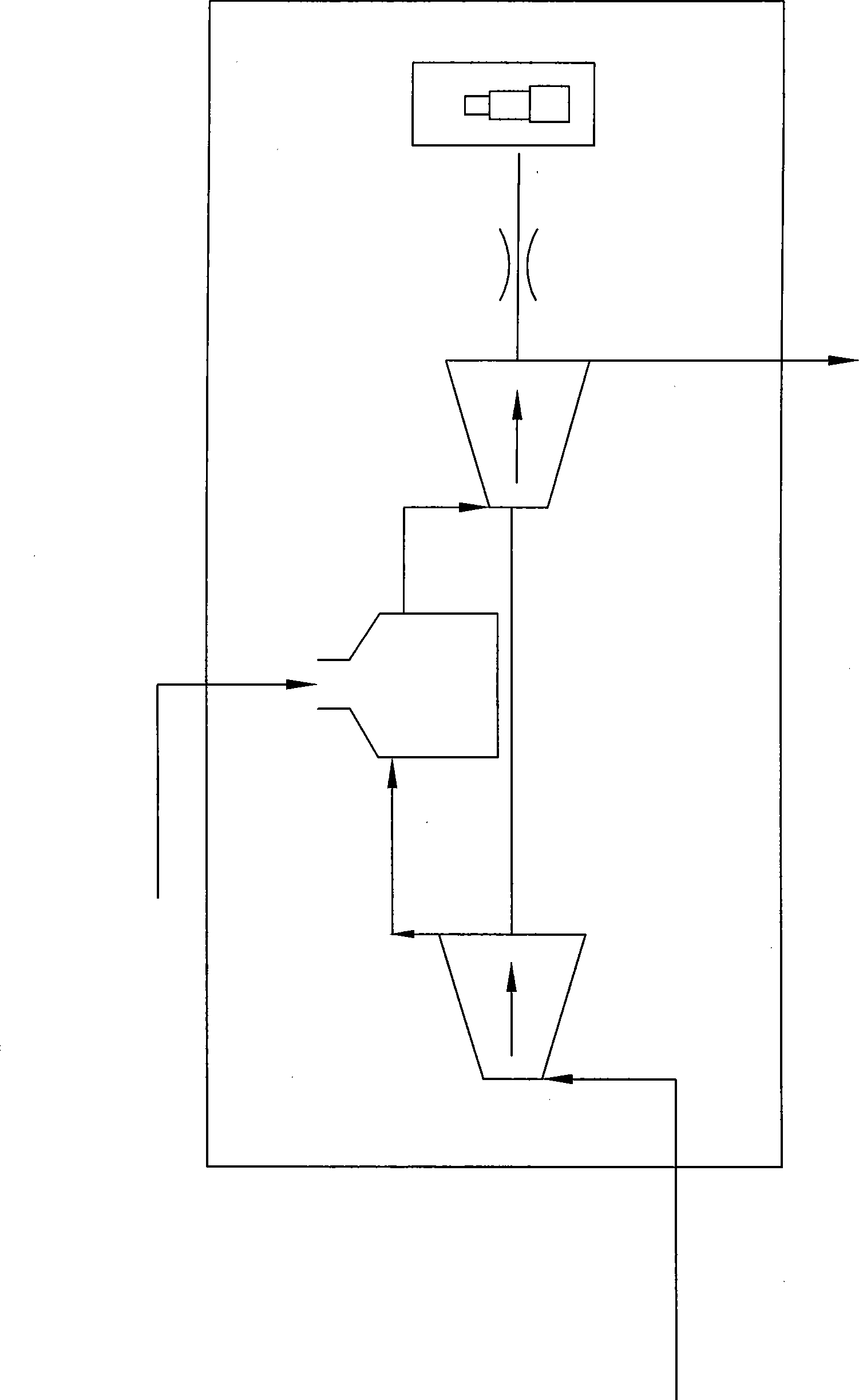
[0013] The working process of the present invention is: two independent electric motors drive the compressor, the high-pressure air generated by compression enters the main pipe for mixing, the mixed air enters the combustion ...


PUM


Abstract

The invention provides a main pipe type micro gas turbine set with two air compressors, which relates to a gas turbine set for generating electricity. The micro gas turbine set solves the problem that the prior micro gas turbine set cannot keep higher running efficiency in a wider load change range. An output shaft of a first motor (8) is connected with an output shaft of a first air compressor (2) through a first lamination coupling (6), an output shaft of a second motor (9) is connected with an output shaft of a second air compressor (3) through a second lamination coupling (7), outputs of the first air compressor (2) and the second air compressor (3) are connected with an inlet of a main pipe (1), an output of the main pipe (1) is connected with an inlet of a combustion chamber (4), an output of the combustion chamber (4) is connected with an inlet of a turbine (5), and an output shaft of the turbine (5) is connected with one end of a third lamination coupling (10). The main pipe type micro gas turbine set achieves the aim of keeping the higher running efficiency in a wider load change range, improves the running performance of the air compressors, and improves the overall economical efficiency of the gas turbine set.

Description

technical field [0001] The invention relates to a gas turbine set for power generation, in particular to a micro gas turbine set for distributed energy applications. Background technique [0002] In the existing micro gas turbine unit, the compressor and the turbine are coaxial (such as image 3 shown), the driving force of the compressor is provided by the turbine. The compressor, combustor, and turbine are used as a whole as a power source, and the shaft power is transmitted to the generator through the coupling, and finally converted into electrical energy to supply power to users. For distributed energy applications, user load characteristics change drastically and there is a huge peak-to-valley difference, which requires its power equipment to provide stable load output within a wide power range. Using the existing micro gas turbine unit as the power equipment of the distributed energy system will face a difficult situation: in order to meet the load needs of users, th...

Claims


Application Information

Patent Timeline
IPC IPC(8): F02C6/00F02C7/00F02C7/05
Inventor 唐井峰于达仁宋英东鲍文徐志强
Owner HARBIN INST OF TECH
Learn More