Phase filtering based beam forming method

A technology of phase filtering and beaming, which is applied in the field of beamforming based on phase filtering, and can solve problems such as increasing the difficulty of subsequent arrival times

Active Publication Date: 2009-08-12
THE 715TH RES INST OF CHINA SHIPBUILDING IND CORP
View PDF0 Cites 11 Cited by
  • Summary
  • Abstract
  • Description
  • Claims
  • Application Information

AI Technical Summary

Problems solved by technology

Therefore, the receiving beam of the conventional beamforming algorithm has a certain width and does not have a steep front, which increases the difficulty of subsequent time of arrival (TOA) estimation

Method used


Image

  • Phase filtering based beam forming method
  • Phase filtering based beam forming method
  • Phase filtering based beam forming method

Examples


Embodiment Construction

[0031] Below in conjunction with specific embodiment and accompanying drawing, the present invention will be further described:

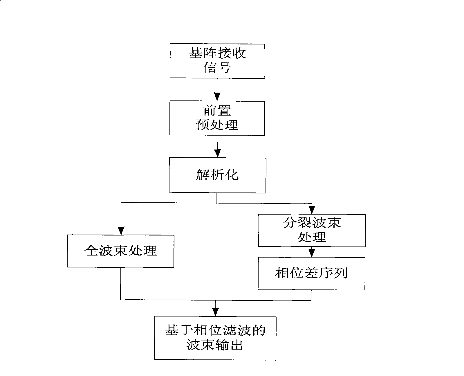
[0032] The flow chart of beamforming in the present invention is as follows figure 1 As shown, this beamforming method based on phase filtering specifically includes the following steps:

[0033] Step 1: Use the received signal of the M-element arbitrary formation receiving array, and perform pre-processing such as time filtering, A / D conversion, and amplification on the received signal of the basic array through the pre-preprocessor. Let the array element numbers be 1, 2, ..., M respectively, then the array element output signal is:

[0034] x(n)=[x 1 (n),x 2 (n),...,x M (n)] T (1)

[0035] where x 1 (n),x 2 (n),...,x M (n) is the output signal of the 1st, 2nd, ..., M array elements, and the superscript "T" means transpose.

[0036] Step 2: Using the Hilbert transform of the signal, the analytical signal of the output signal of the...


PUM


Abstract

The invention relates to the field of sonar signal processing, in particular to a phase filtration-based beam forming method. In the method, the result of beam forming is subjected to phase filtration according to a phase difference sequence of split beams so as to form a phase filtration-based beam forming output. The novel phase filtration-based beam forming method provided by the invention has the advantages of making full use of phase information, narrowing the major lobes of beams, suppressing reverberation return signals in directions excluding the directions of the main axes of the beams as much as possible, improving the precision of the estimation of the time of arrival (TOA) of following waves, along with simple calculation method, small calculated amount and easy implementation.

Description

technical field [0001] The invention relates to the field of sonar signal processing, in particular to the field of multi-beam sonar array signal processing, and mainly relates to a beam forming method based on phase filtering. Background technique [0002] Beamforming is a hot research problem in sonar signal processing. The beamforming system is the core component of the modern sonar system, and it is the basis for the good tactical and technical performance of the sonar. Coventional beamforming (CBF for short) is a classic method in array signal processing. It has a simple structure, is easy to implement, and has good adaptability to various harsh environments. [0003] Multi-beam sonar receives seabed backscatter signals with the same frequency from different directions, its intensity attenuates with the decrease of grazing angle, and changes with seabed bottom and inclination angle, the echo of a certain sampling point on the seabed The signal is a scattered wave over...

Claims


Application Information

Patent Timeline
Patent Type & Authority Applications(China)
IPC IPC(8): G01S7/52
Inventor 丁烽胡鹏祝恒年汪素萍高博
Owner THE 715TH RES INST OF CHINA SHIPBUILDING IND CORP
Why Eureka
Try Eureka