Bi-stable acceleration induction micro-switch based adhesion

A technology of acceleration sensing and micro-switching, which is applied in the direction of electric switches, coupling of optical waveguides, and components of TV systems, etc. Mis-off and other issues, to achieve the effect of improving conduction reliability, avoiding external disturbance, and easy assembly

Inactive Publication Date: 2009-08-12
XIDIAN UNIV
View PDF0 Cites 6 Cited by
  • Summary
  • Abstract
  • Description
  • Claims
  • Application Information

AI Technical Summary

Problems solved by technology

In the "on" state, when there is an external disturbance acceleration, the sensing mass block will move against the elastic force, even if the threshold sensing acceleration does not reach the design requirement, the sensing mass block will also move, resulting in micro-switches prone to " Mis-closed, leading to accidents
[0006] 2) Unable to achieve steady state "off" state
This leads to the possibility of "wrong closing" of the micro switch
[0010] 2) "Transient closure" problem
However, the movable electrode 24 of the mass block is quickly pulled back by the spring, resulting in the problem that the stable closing has not been realized and then immediately disconnected, that is, the "transient closing" problem
Since there is contact resistance at the contact point between the fixed electrode 23 of the elastic beam and the movable electrode 24 of the mass block, that is, the thin film resistance and the contraction resistance, this "transient closing" process is difficult to ensure the stable closing requirements of the external circuit

Method used


Image

  • Bi-stable acceleration induction micro-switch based adhesion
  • Bi-stable acceleration induction micro-switch based adhesion
  • Bi-stable acceleration induction micro-switch based adhesion

Examples


Embodiment 1

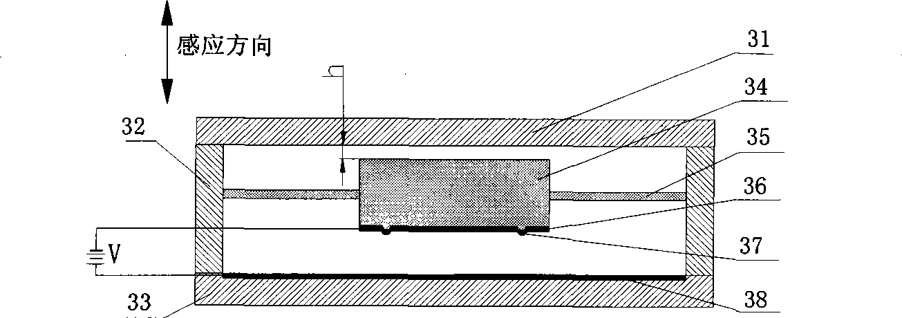
[0029] Embodiment 1, the inductive micro switch of the present invention consists of three parts: a frame body, an inductive component and an electrode plate. Wherein the frame body is composed of the left and right frames 32, the upper top cover 31 and the lower bottom cover 33 to form an airtight cavity; the sensing part is composed of a sensing mass 34 and a support beam 35, both of which are photolithographically integrated, and the support beam 36 adopts two ends. The straight beam structure is fixed on the frame 32, and the distance h between the mass block 34 and the upper top cover 31 is 1 μm. A gold film is deposited on the lower part of the mass block 34 to form a movable plate 36, and two hemispherical contacts 37 are arranged on the movable plate 36; a gold film is deposited on the inner side of the lower bottom cover 33 to form a fixed plate 38 . The gap between the movable plate 36 and the fixed plate 38 is 10 μm, and a DC voltage of 26V is passed between the tw...

Embodiment 2

[0030]Embodiment 2, the inductive micro switch of the present invention consists of three parts: a frame body, an inductive component and an electrode plate. Wherein the frame body is composed of the left and right frames 32, the upper top cover 31 and the lower bottom cover 33 to form an airtight cavity; the sensing part is composed of a sensing mass 34 and a support beam 35, both of which are photolithographically integrated, and the two ends of the support beam are The straight beam structure is fixed on the frame 32, and the distance h between the mass block 34 and the upper top cover 31 is 0.6 μm. A gold film is deposited on the lower part of the mass block 34 to form a movable plate 36, and two hemispherical contacts 37 are arranged on the movable plate 36; a gold film is deposited on the inner side of the lower bottom cover 33 to form a fixed plate 38 . The gap between the movable plate 36 and the fixed plate 38 is 10 μm, and a DC voltage of 26V is passed between the t...

Embodiment 3

[0031] Embodiment 3, the inductive micro switch of the present invention consists of three parts: a frame body, an inductive component and an electrode plate. Wherein the frame body is composed of the left and right frames 32, the upper top cover 31 and the lower bottom cover 33 to form an airtight cavity; the sensing part is composed of a sensing mass 34 and a support beam 35, both of which are photolithographically integrated, and the two ends of the support beam are The straight beam structure is fixed on the frame 32, and the distance h between the mass block 34 and the upper top cover 31 is 0.1 μm. A gold film is deposited on the lower part of the mass block 34 to form a movable plate 36, and two hemispherical contacts 37 are arranged on the movable plate 36; a gold film is deposited on the inner side of the lower bottom cover 33 to form a fixed plate 38 . The gap between the movable plate 36 and the fixed plate 38 is 10 μm, and a DC voltage of 26V is passed between the ...


PUM


Abstract

The invention discloses an adhesion-based bistable acceleration sensing micro-switch, which belongs to the field of micro-electronic components and mainly solves the problems of 'error off' and 'transient close' of the prior micro-switch. The micro-switch comprises a sensing mass block (34), a bearing beam (35) and a framework (32), wherein two ends of the bearing beam are fixed on the framework; the upper surface and the lower surface of the framework are fixed with an upper top cover (31) and a lower bottom cover (33) respectively; the distance between the mass block and the upper top cover is controlled to be between 0.1 and 1 mu m; the lower part of the mass block (34) is deposited with a gold film to form a movable pole plate (35); the inner side of the lower bottom cover is deposited with a gold film to form a fixed pole plate (38); and the movable pole plate is provided with two semi-spherical structural contacts (37). When the micro-switch is in an 'on' state, the mass block (34) is tightly adhered to the upper top cover (31), and when the micro-switch is in an 'off' state, the mass block (34) is tightly adhered to the lower bottom cover (33). The micro-switch has the advantages of strong anti-interference and stable conduction, and can be applied to the fields of vehicle safety air bags, anti-locking systems and household appliance triggering.

Description

technical field [0001] The invention belongs to the technical field of electronic components, in particular to an inductive micro switch, which can be used in safety airbags and anti-lock braking systems of automobiles. technical background [0002] The inductive micro switch is processed by micro-electro-mechanical system (MEMS for short) technology, which can sense acceleration, and is controlled by the acceleration threshold value, and performs switching action through multi-force coupling. It integrates sensing, control and execution, and has the characteristics of small size, high reliability, and simple structure. Therefore, it has a strong demand in trigger fields such as aerospace systems, automotive airbags and anti-lock braking systems, and household appliances. . [0003] In 2004, the Vienna University of Technology developed a dual-mass-spring inductive microswitch [Alexander R. Neuhaus, Werner F. Rieder, and Martin Hammerschmidt, Influence of Electrical and Mec...

Claims


Application Information

Patent Timeline
Patent Type & Authority Applications(China)
IPC IPC(8): H01H35/14H01H59/00B81B7/02
Inventor 田文超杨银堂
Owner XIDIAN UNIV
Why Eureka
Try Eureka