Compressed-air-storing electricity generating system and electricity generating method using the same

A technology of compressed air and power generation system, which is applied in the field of law, and can solve problems such as reduction and reduction in turbine driving efficiency

Inactive Publication Date: 2009-08-12
KOREA INST OF MASCH & MATERIALS
View PDF0 Cites 44 Cited by
  • Summary
  • Abstract
  • Description
  • Claims
  • Application Information

AI Technical Summary

Problems solved by technology

However, since the compressed air is continuously discharged to the outside, the pressure in the storage tank 30 gradually decreases

Method used


Image

  • Compressed-air-storing electricity generating system and electricity generating method using the same
  • Compressed-air-storing electricity generating system and electricity generating method using the same
  • Compressed-air-storing electricity generating system and electricity generating method using the same

Examples


Embodiment Construction

[0019] Now, the compressed air energy storage power generation system according to the present invention will be described in detail with reference to the accompanying drawings.

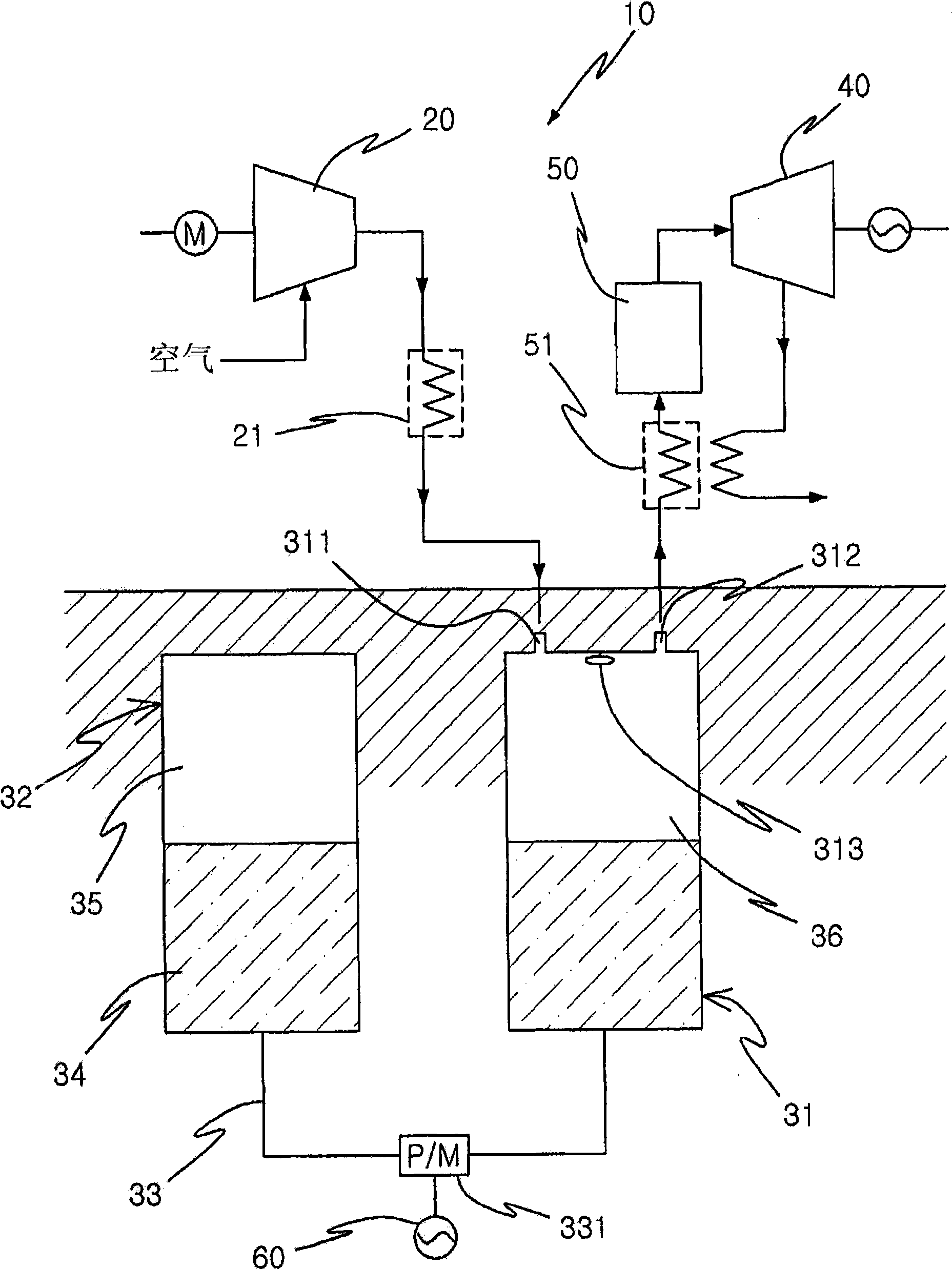
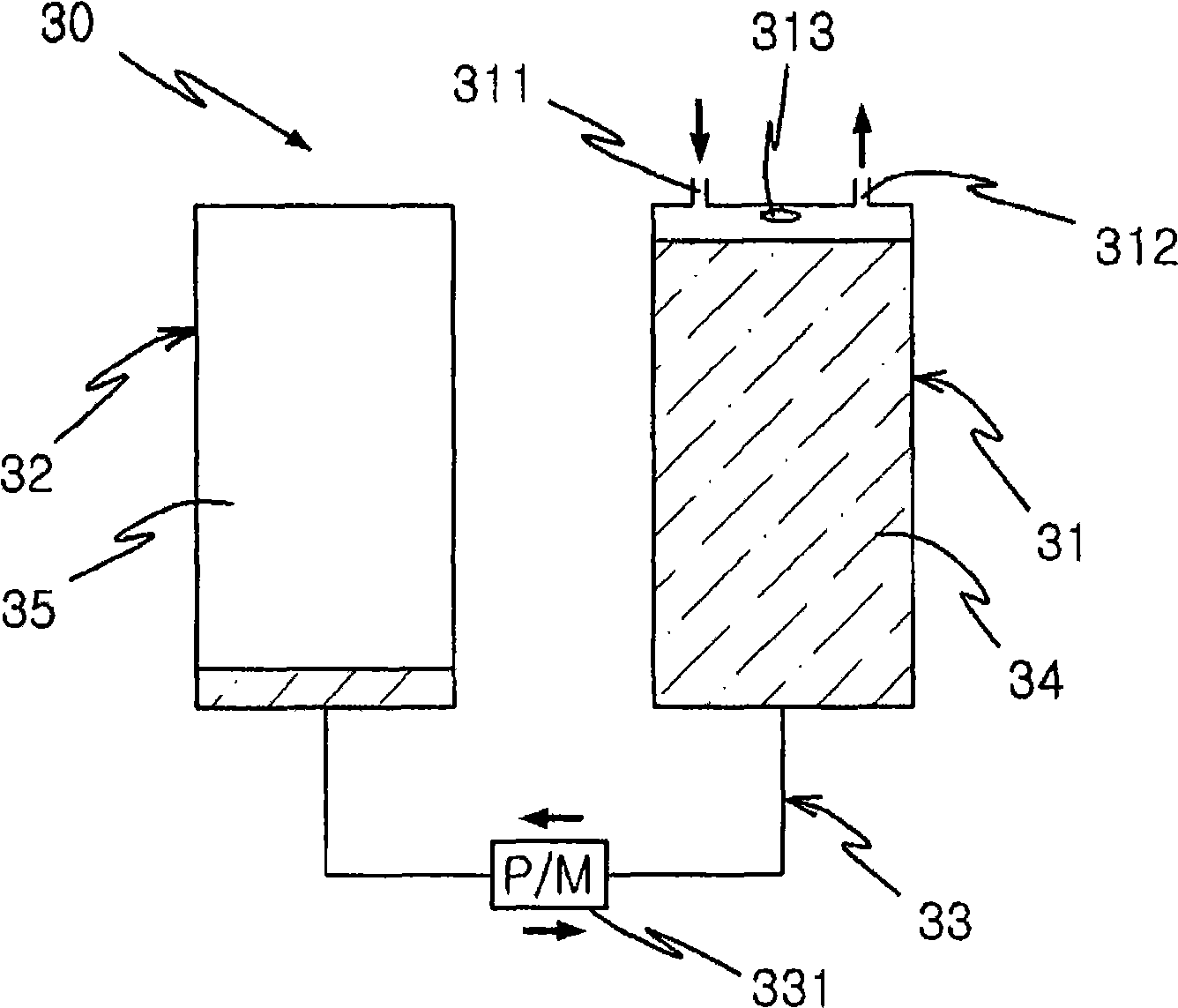
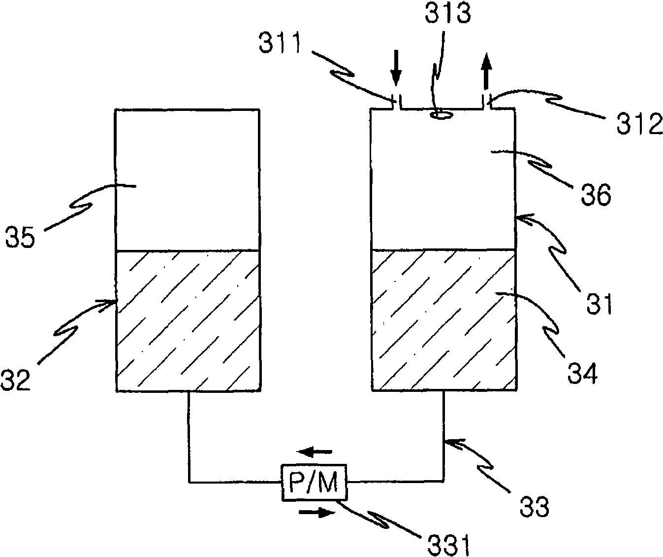
[0020] figure 1 To represent a schematic diagram of a compressed air energy storage power generation system according to the present invention, Figure 2 to Figure 4 is a schematic diagram showing the pressure change in the storage tank of the compressed air energy storage power generation system according to the present invention, Figure 5 It is a block diagram showing a power generation method using the compressed air energy storage power generation system according to the present invention.

[0021] Such as figure 1 As shown, the compressed air energy storage power generation system 10 of the present invention includes a compressor 20 , a storage tank 30 storing air compressed by the compressor 20 , and a turbine 40 driven by the compressed air discharged from the storage tank 30 .

[0022] ...


PUM


Abstract

Disclosed are a compressed air energy-storing electricity generating system and an electricity generating method using the same, in which air of a high pressure is injected into a tank laid under the ground using midnight electricity and surplus produced electricity, and the air of the high pressure in the tank is uniformly discharged so as to drive a generator during a time period when the consumption of electric power is high, thus efficiently managing energy.

Description

technical field [0001] The present application relates to a compressed air energy storage power generation system and a power generation method using the system, and more particularly, to a compressed air energy storage power generation system and a power generation method using the same, wherein nighttime power and excess produced Electricity, injecting high-pressure air into a tank placed underground, and uniformly discharging this high-pressure air in the tank during periods of high power consumption to drive a generator, thereby efficiently managing energy. Background technique [0002] Nighttime power is electricity used at night when power consumption is low, from 10:00 p.m. of one day to 8:00 a.m. Electricity is oversupplied and therefore cheaper. Therefore, various methods of using nighttime power have been proposed. Typical installations that use nighttime electricity include regenerative boilers that use nighttime electricity and regenerative water heaters that u...

Claims


Application Information

Patent Timeline
IPC IPC(8): F01B29/00
CPCY02E60/15Y02E60/17Y02E10/28F04F1/06F02C6/16F02C6/18Y02E10/30Y02E60/16F01B29/00F01B29/02F01B31/00Y02E10/20
Inventor 金英敏D·法拉特申东吉曹圭伯
Owner KOREA INST OF MASCH & MATERIALS
Why Eureka
Try Eureka