
Backlight device and display device using same

A technology for a backlight device and a display unit, which is applied to the cooling/heating device, lighting device, circuit heating device, etc. of the lighting device, can solve the problems of insufficient suppression, difficulty in achieving luminous efficiency and luminous quality, and achieves the effect of effective heat dissipation

Inactive Publication Date: 2009-08-12
SHARP KK
View PDF3 Cites 10 Cited by
  • Summary
  • Abstract
  • Description
  • Claims
  • Application Information

AI Technical Summary

Problems solved by technology

Therefore, in the conventional backlight device, there is a problem that the ambient temperature rise due to the heat from the light-emitting diodes cannot be sufficiently suppressed, and it is difficult to improve the luminous efficiency and the luminous quality.

Method used


Image

  • Backlight device and display device using same
  • Backlight device and display device using same
  • Backlight device and display device using same

Examples


no. 1 Embodiment approach

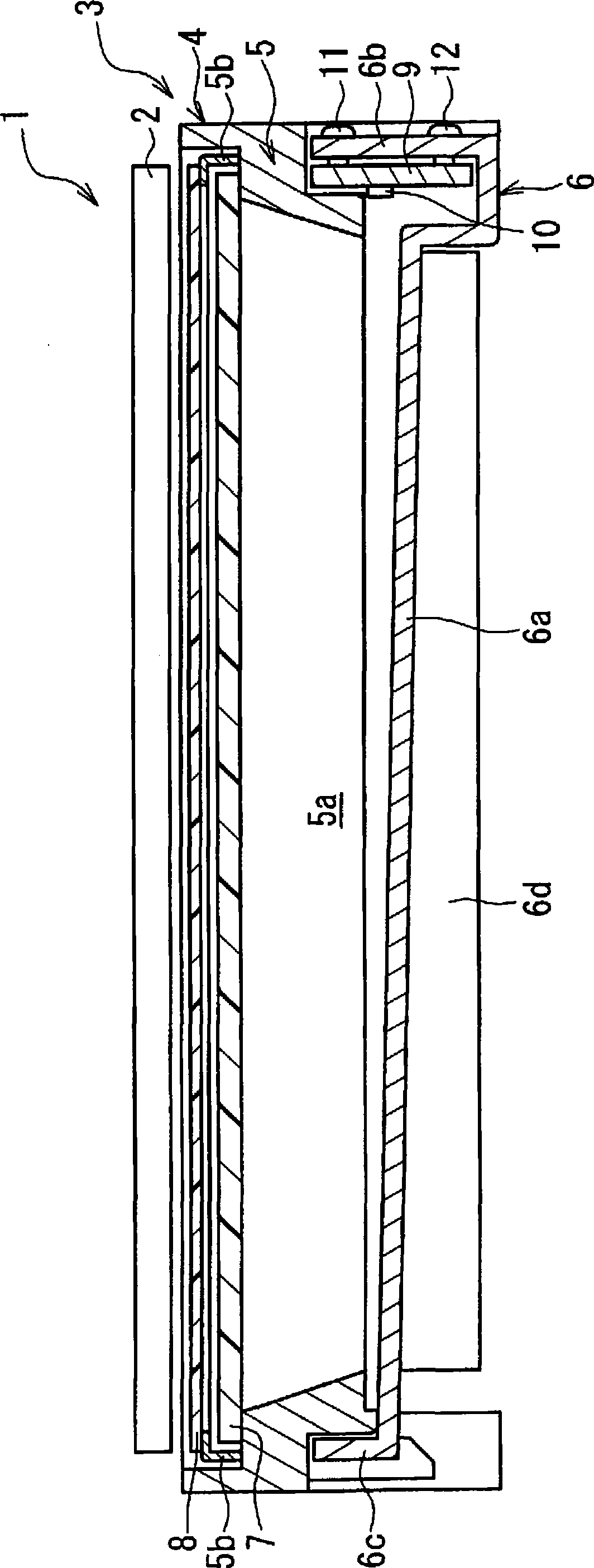
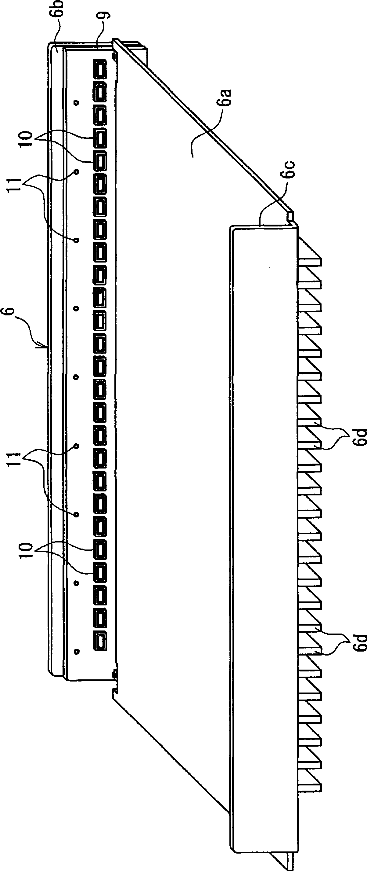
[0054] figure 1 It is a cross-sectional view showing the configuration of main parts of the backlight device and the liquid crystal display device according to the first embodiment of the present invention. exist figure 1 Among them, the liquid crystal display device 1 of this embodiment is provided with a liquid crystal panel 2 and a backlight device 3 of the present invention, wherein the liquid crystal panel 2 is a display section whose upper side in the figure is set as the viewing side (display surface side). The backlight device 3 is disposed on the non-display surface side of the liquid crystal panel 2 (lower side in the drawing), and generates illumination light for illuminating the liquid crystal panel 2 .

[0055] The liquid crystal panel 2 includes a liquid crystal layer and a drive circuit (not shown) for driving the liquid crystal layer in units of pixels. The light is used to form the desired image on the display surface. In addition, the liquid crystal pane...

no. 2 Embodiment approach

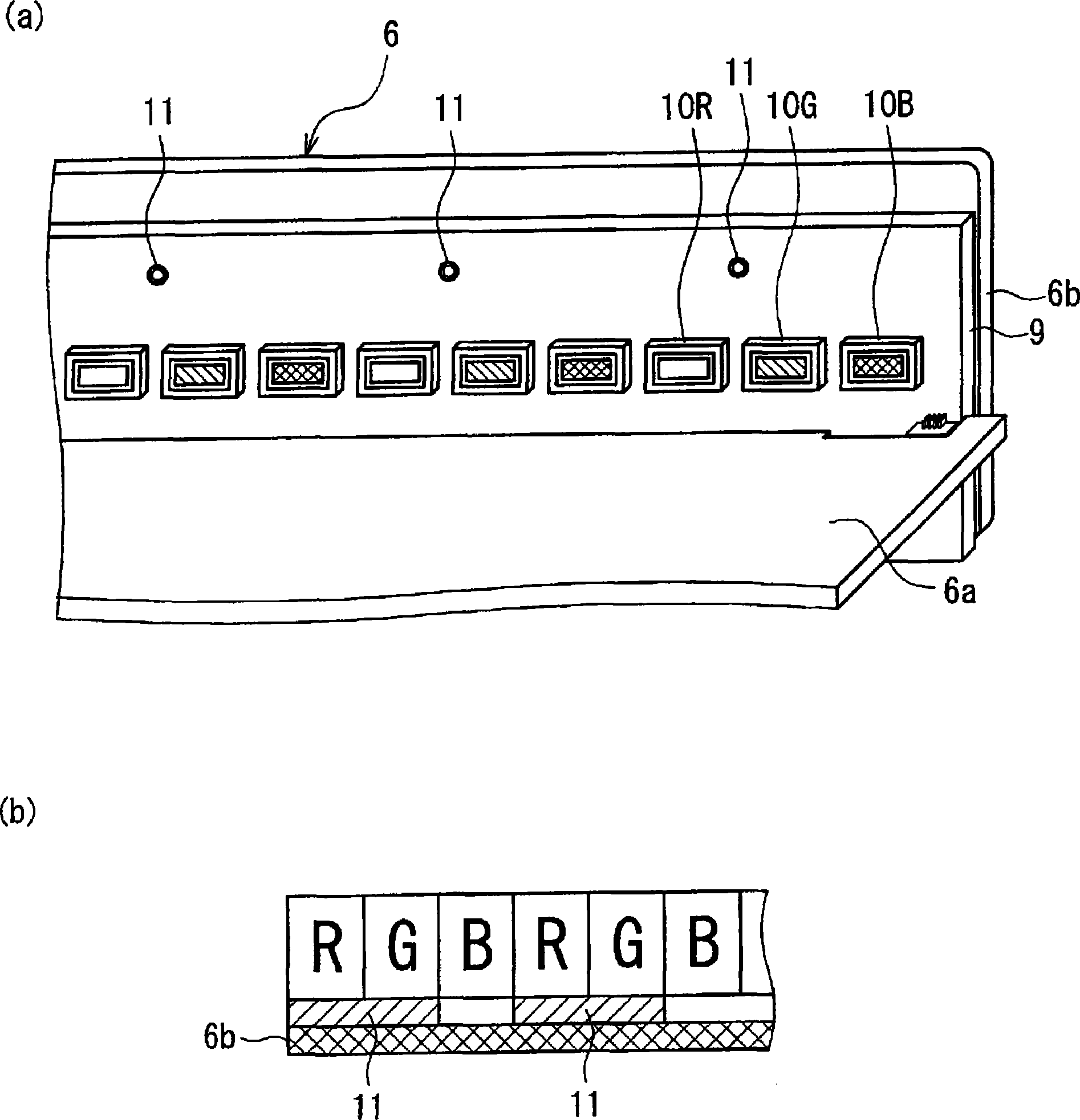
[0081] Figure 4 It is a figure explaining the main part structure of the backlight device concerning 2nd Embodiment of this invention, (a) is an enlarged perspective view which shows the mounting part of a light emitting diode, (b) is a figure explaining the arrangement example of a light emitting diode. In the drawings, the main difference between this embodiment and the above-mentioned first embodiment is that a plurality of light emitting diodes are arranged on the substrate so that the blue light emitting diodes are adjacent to the red light emitting diodes or the green light emitting diodes. In addition, the same code|symbol is attached|subjected to the element common to the said 1st Embodiment, and the overlapping description is abbreviate|omitted.

[0082] That is, if Figure 4 As shown in (a) and (b), on the substrate 9 of this embodiment, the blue light emitting diode 10b is provided next to the red light emitting diode 10r or the green light emitting diode 10g. Th...


PUM


Abstract

A backlight device (3) is provided with a substrate (9) whereupon a plurality of light emitting diodes (10) are arranged, and a lower side chassis (heat dissipating section) (6) where heat generated in the light emitting diodes (10) is transferred from the substrate (9) and dissipated to the external. A heating value of each light emitting diode (10) is previously measured, and based on the measurement results of the heating values, an arrangement position on the substrate (9) is determined and corresponding light emitting diodes (10) are arranged.

Description

technical field [0001] The present invention relates to a backlight device, and more particularly, to a backlight device having a light emitting diode used as a light source and a display device using the same. Background technique [0002] In recent years, for example, liquid crystal display devices have been widely used in liquid crystal televisions, monitors, mobile phones, and the like as flat panel displays that are thinner and lighter than conventional cathode ray tubes. Such a liquid crystal display device includes a backlight device emitting light and a liquid crystal panel displaying a desired image by shuttering light from a light source provided on the backlight device. [0003] In addition, among the above-mentioned backlight devices, edge-light or direct-type backlight devices in which linear light sources composed of cold-cathode tubes or hot-cathode tubes are arranged on the side or under the liquid crystal panel have been provided. However, mercury is contai...

Claims


Application Information

Patent Timeline
Patent Type & Authority Applications(China)
IPC IPC(8): F21V29/00G02F1/13357F21S2/00F21Y101/02G02F1/1335
CPCG02F1/133603G02B6/0068G02F2001/133628H05K1/0203G02F1/133615H05K1/18G02B6/0085G02B6/0091G02F1/133628
Inventor 日登荣治
Owner SHARP KK
Learn More