Cylinder for a printing unit of a printing machine and method for swapping out the printing sleeve of such a cylinder

A technology for printing sleeves and printing presses, which is applied to general parts of printing machinery, printing presses, rotary printing presses, etc.

Inactive Publication Date: 2009-08-19
MULLER MARTINI HLDG
View PDF4 Cites 14 Cited by
  • Summary
  • Abstract
  • Description
  • Claims
  • Application Information

AI Technical Summary

Problems solved by technology

The danger here is that the clamping sleeve and thus the embossing plate are only sufficiently fixed on one side, which correspondingly impairs or even renders the subsequent embossing process impossible.

Method used


Image

  • Cylinder for a printing unit of a printing machine and method for swapping out the printing sleeve of such a cylinder
  • Cylinder for a printing unit of a printing machine and method for swapping out the printing sleeve of such a cylinder
  • Cylinder for a printing unit of a printing machine and method for swapping out the printing sleeve of such a cylinder

Examples


Embodiment Construction

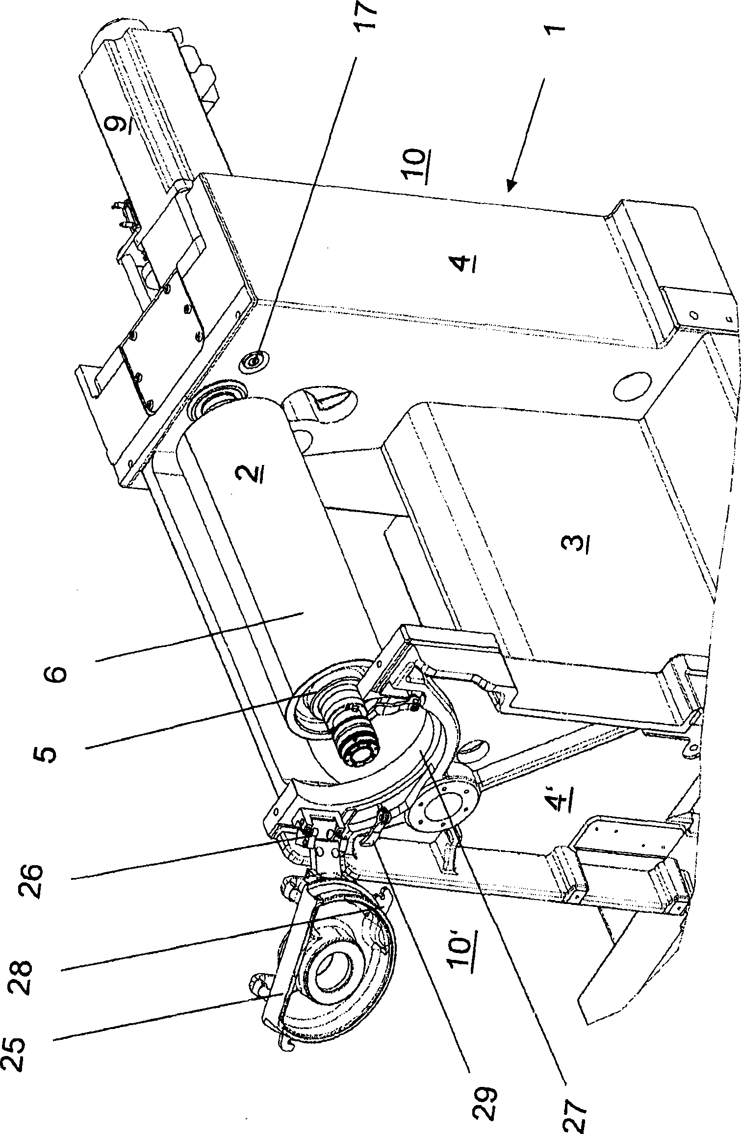
[0029] figure 1 A side view of the printing unit 1 of an offset printing press is shown, limited to the parts necessary for understanding the invention. Furthermore, the printing unit 1 is provided with a cylinder 2 , of which a blanket cylinder is shown, for example, here. The printing unit 1 has a housing 3 with two side panels 4 , 4 ′ for supporting the cylinder 2 . The other parts that also belong to the printing unit 1 , such as the plate and impression cylinders as well as the coloring and dampening units, are not shown for reasons of better simplicity.

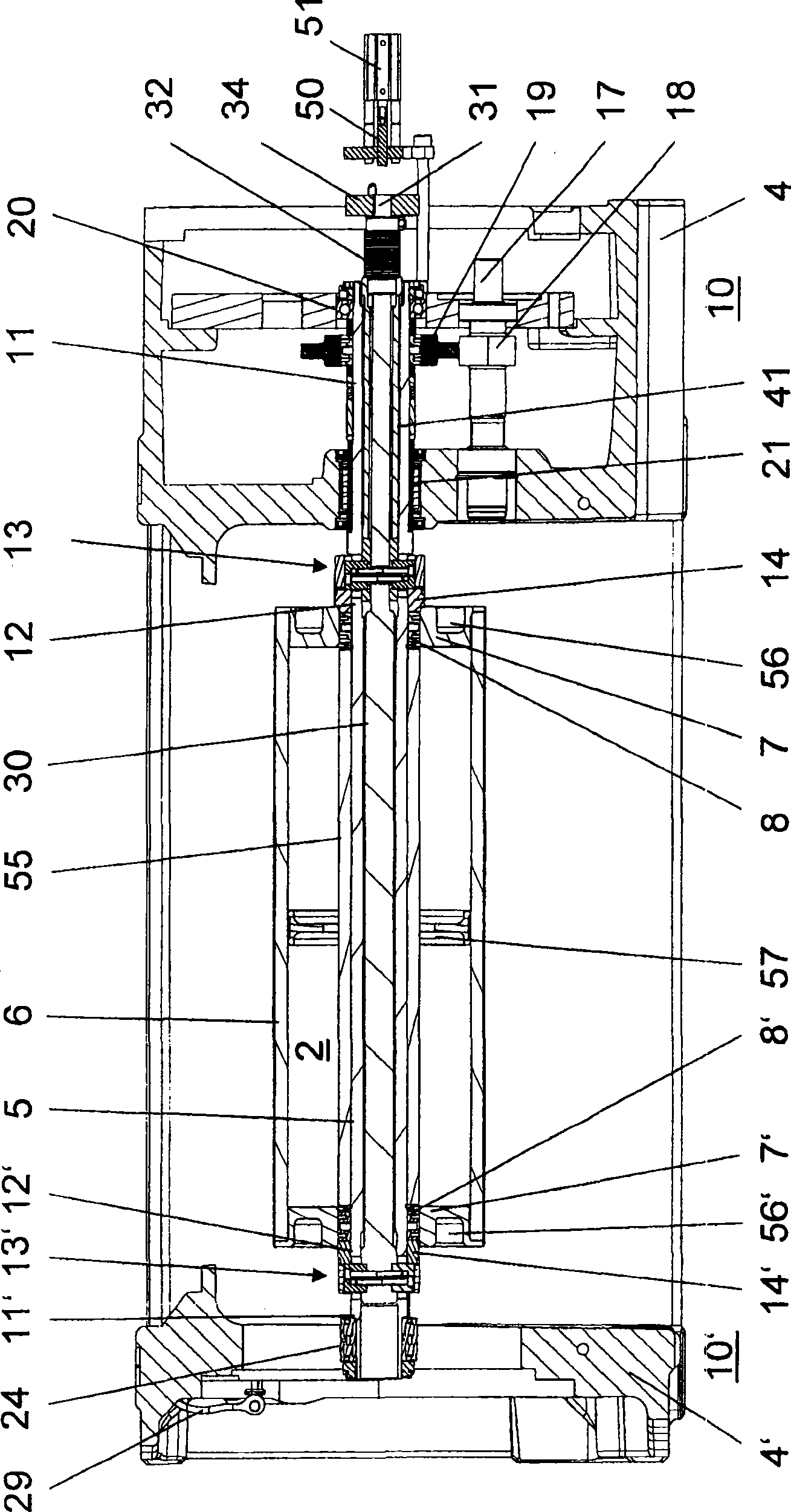
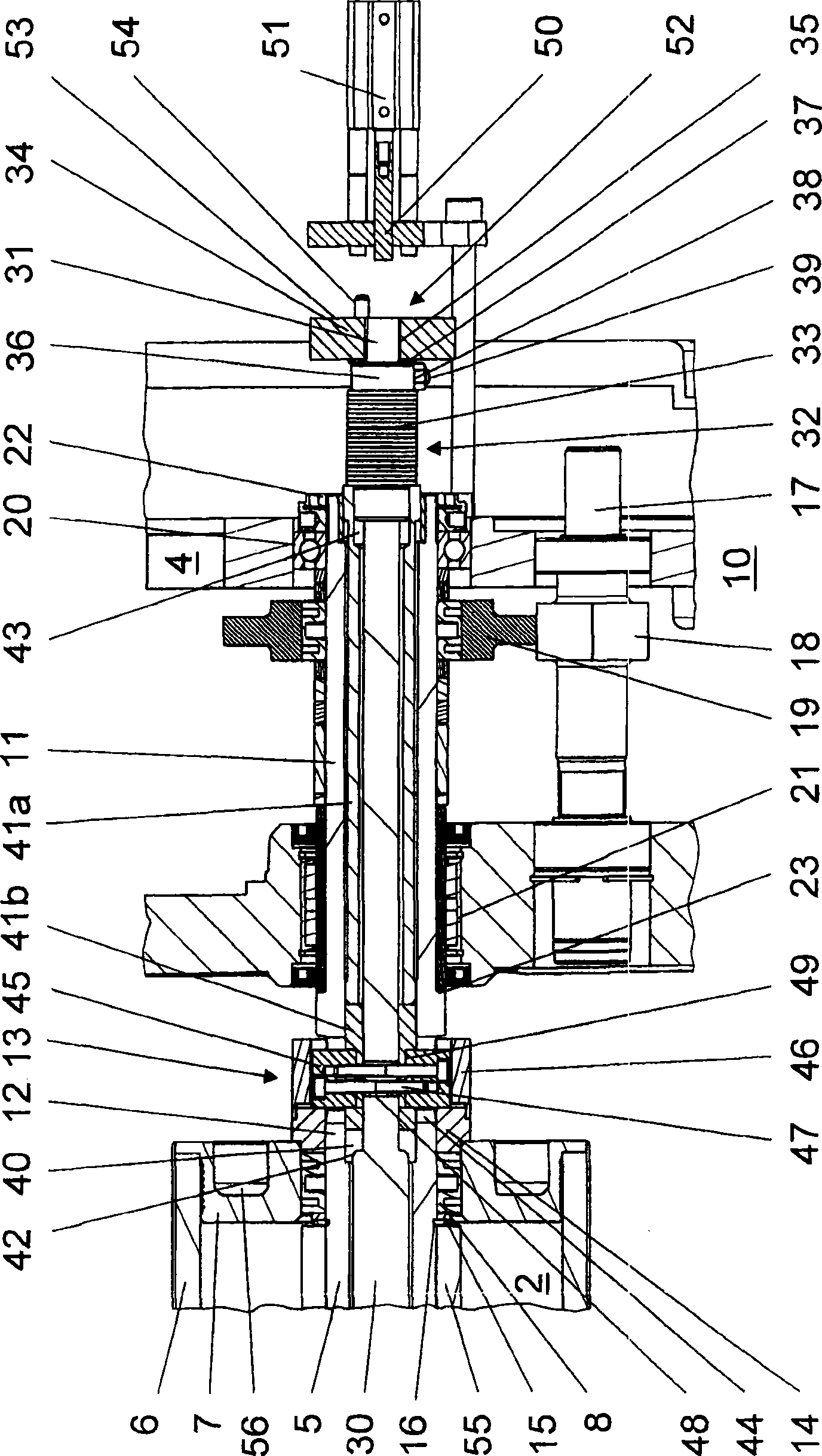
[0030] The cylinder 2 consists of a cylinder core designed as a bearing shaft 5 to which a printing plate part designed as a printing sleeve 6 is detachably connected. The printing sleeve 6 has at its two end faces a respectively inserted support ring 7, 7', which in the installed state is supported by a first clamping sleeve designed as a clamping sleeve sitting on the support shaft 5. Or the second clamping part 8,...


PUM


Abstract

A cylinder for a printing unit of a printing machine includes a hollow support shaft (5) with first and second tensioning elements (8, 8') arranged thereon at a distance to each other. A replaceable printing sleeve (6) is positioned on the support shaft. First and second force transfer elements (13, 13') respectively cooperate with the first and the second tensioning elements (8, 8') for clamping down and releasing the printing sleeve (6). An operating mechanism (30) is arranged on the inside of the hollow support shaft (5) and is operatively connected to the two force transfer elements (13, 13'). The operating mechanism includes at least one energy-storage element (32) for tightening and releasing the two tensioning elements (8, 8').

Description

technical field [0001] The invention relates to a cylinder for a printing unit of a printing press, the cylinder having a support shaft on which first and second clamping parts are arranged at a distance from each other, exchangeable printing sleeves supported on the first and second On the second clamping part, the cylinder also has a first and a second transmission element, which respectively cooperate with the first or second clamping part for clamping and releasing the printing sleeve. Furthermore, the invention relates to a method for exchanging a printing sleeve of such a cylinder. Background technique [0002] For successively different printing jobs, the equipment of the printing press, ie the cylinders of its printing units, must be changed accordingly. In order to avoid complicated cylinder changes, cylinders are now used which have a rotatable support shaft designed as a cylinder core and a printing sleeve which is releasably fastened to the cylinder core and car...

Claims


Application Information

Patent Timeline
Patent Type & Authority Applications(China)
IPC IPC(8): B41F13/20B41F27/14
CPCB41P2217/15B41P2227/21B41F13/08
Inventor S·贝耶斯多夫
Owner MULLER MARTINI HLDG
Why Eureka
Try Eureka