
Seep guide apparatus for automatically removing water in soil
A soil and automatic technology, which is applied in the fields of soil protection, construction, and infrastructure engineering, etc., can solve problems such as easy blockage, direct infiltration and output of infiltration water, and inability to resist multi-terminal changes in the water environment. Reduce water content and accumulated water, simple construction, and prevent clogging and silting effects
- Summary
- Abstract
- Description
- Claims
- Application Information
AI Technical Summary
Problems solved by technology
Method used
Image

Examples
Embodiment Construction
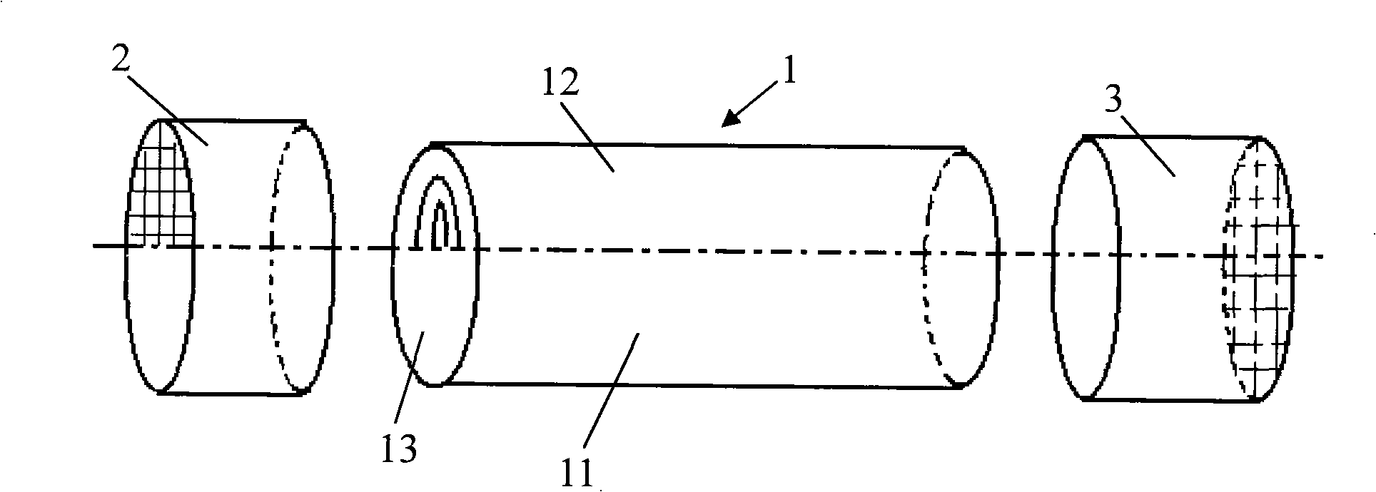
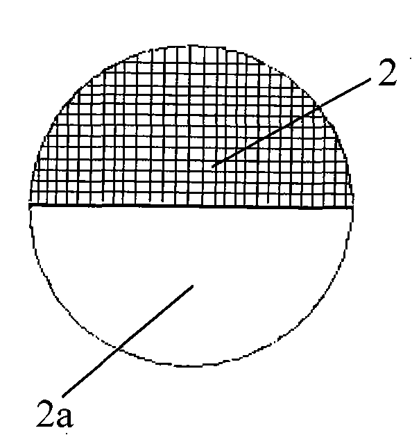
[0024] see figure 1 , in the specific implementation, the entire infiltration device is set into three sections, that is, the central infiltration pipe 1 as the main infiltration guide, the water outlet end caps 2 and the tail end caps 3 located at both ends respectively; the three parts are connected to form a whole.
[0025] figure 1 As shown, the lower half of the central permeation pipe 1 is set as an impermeable water collecting tank 11, which adopts a thin-walled structure, the upper half is a water-permeable filter layer 12, and the two ends are a filter screen 13;
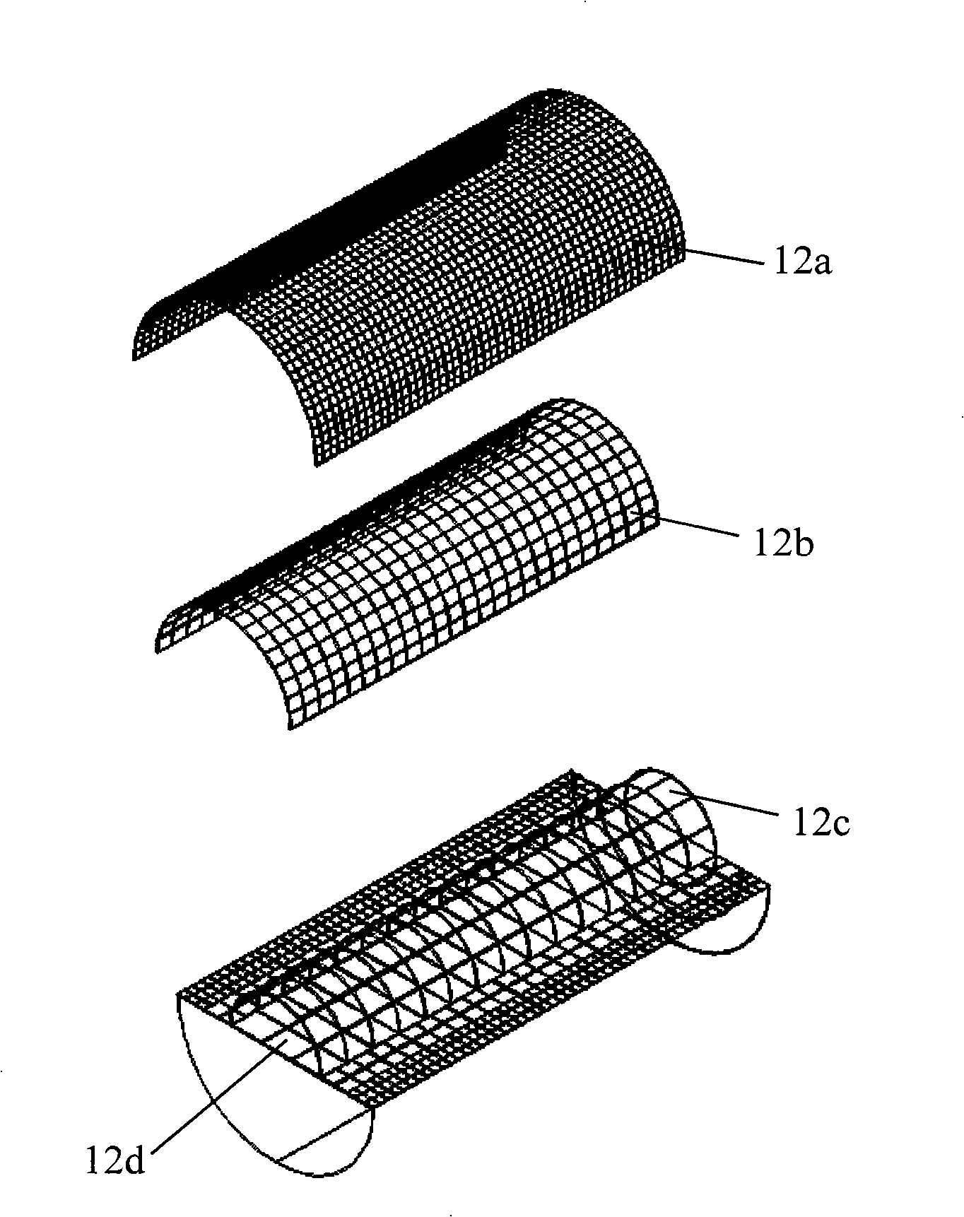
[0026] figure 2 As shown, in this embodiment, the upper half of the water permeable filter layer 12 of the middle infiltration tube 1 is set as a multi-layer filter screen, including an outer layer filter screen 12a, a middle layer filter screen 12b, an inner layer filter screen 12c and a flat layer filter screen 12d, the position of the leveling filter screen 12d in the pipe body can be centered, or it ...
PUM
 Abstract
Description
Claims
Application Information