Electric-controlled micro valve implemented by shape memory alloy
A memory alloy, electronically controlled technology, used in lift valves, valve details, multi-way valves, etc., can solve the problems of difficult modification and complex structure, and achieve the effect of small size, reduced volume and weight, and large modification space.
- Summary
- Abstract
- Description
- Claims
- Application Information
AI Technical Summary
Problems solved by technology
Method used
Image
Examples
specific Embodiment approach 1
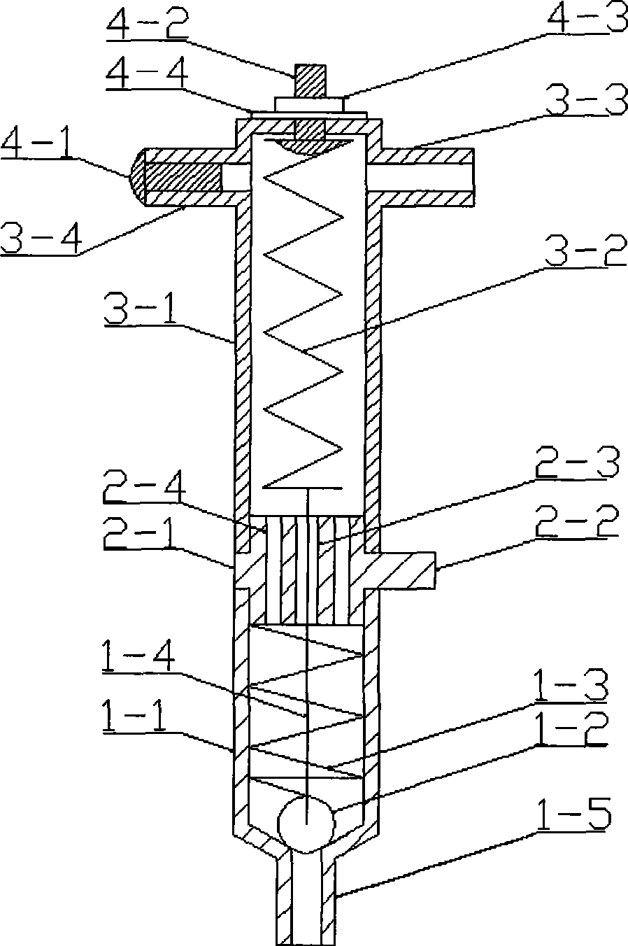
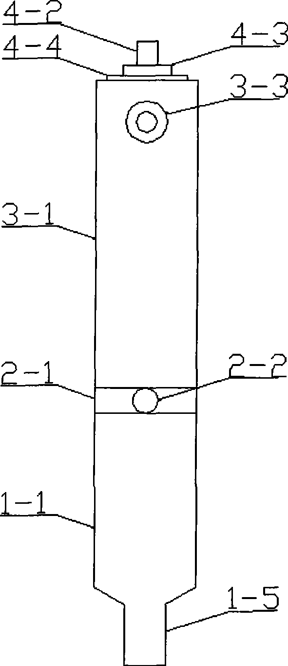
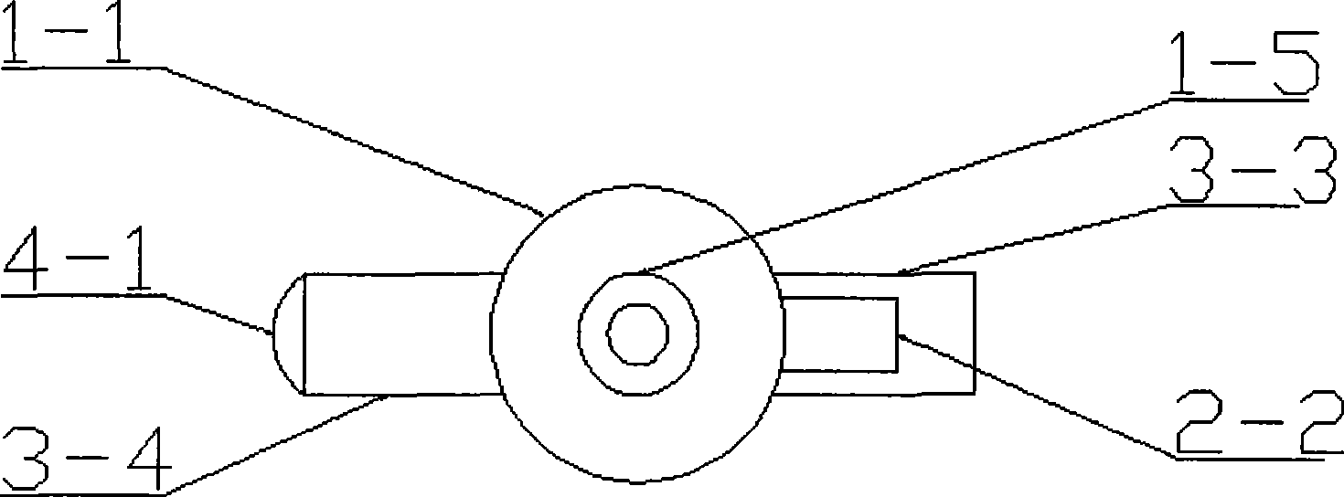
[0068] Specific implementation mode one: see Figure 9 ~ Figure 13, this embodiment is a common general application mode. The main structure includes liquid spray pipe body 1-1, valve ball 1-2, bias pressure spring 1-3, linkage wire 1-4, spout pipe 1-5, separation layer 2-1, terminal post 2-2, Thread hole 2-3, liquid hole 2-4, liquid inlet pipe body 3-1, shape memory alloy driver 3-2, liquid inlet branch pipe 3-3, exhaust branch pipe 3-4, exhaust pipe sealing bolt 4 -1, top fixing bolt 4-2, top fixing nut 4-3, sealing gasket 4-4. The liquid inlet pipe body 3-1 and the liquid spray pipe body 1-1 are connected to the upper and lower ends of the separation layer 2-1 by threads to form the valve body of the valve; the shape memory alloy driver 3-2 serves as the core driving force provider, and one end of it is passed through The top fixing bolt 4-2, the top fixing nut 4-3 and the sealing gasket 4-4 are fixed on the inner top of the liquid inlet pipe body 3-1, and the bottom ring...
specific Embodiment approach 2
[0072] Specific implementation mode two: see Figure 14 ~ Figure 18 , which is an improved solution for the design form in the first specific embodiment. Although the design in the specific embodiment 1 is simple and feasible, there is a problem of inflexibility in application. In this specific embodiment, the structure is as Figure 14 As shown, the main structure is basically the same as that described in Embodiment 1 and its connection method: it still includes a liquid spray pipe body 1-1, a valve ball 1-2, a biasing pressure spring 1-3, and a linkage wire 1- 4. Spout pipe 1-5, separation layer 2-1, terminal post 2-2), thread hole 2-3, liquid hole 2-4, liquid inlet pipe body 3-1, shape memory alloy driver 3-2 , liquid inlet branch pipe 3-3, exhaust branch pipe 3-4, exhaust pipe sealing bolt 4-1, top fixing bolt 4-2, top fixing nut 4-3, sealing gasket 4-4, but it also increases The liquid inlet pipe lower liquid branch pipe 7-1 and the liquid spray pipe upper liquid bran...
Embodiment approach
[0075] The second sub-implementation mode: as Figure 17 As shown, the feature of this method is that when the liquid is initially added, the way of liquid intake is different from that described in Embodiment 1. At this time, the exhaust branch pipe 3-4 on the liquid inlet pipe body 3-1 must be sealed Get up, and at the same time use bolts to tighten and seal the upper liquid branch pipe 7-2 of the liquid spray pipe. After the liquid flows in from the liquid inlet branch pipe 3-3, when there is liquid flowing out from the liquid inlet pipe lower liquid branch pipe 7-1, it means that the liquid has passed. The inner cavity of the entire spray pipe body 1-1 is filled, and the liquid hole 2-4 of the separation layer 2-1 is unblocked. Since the through hole of the liquid branch pipe 7-1 under the liquid inlet pipe is close to the separation layer 2-1, the water liquid will basically not submerge the shape memory alloy driver 3-2 at this time. Then fasten and seal the lower fluid...
PUM
 Abstract
Description
Claims
Application Information
 - R&D
- Intellectual Property
- Life Sciences
- Materials
- Tech Scout
- Unparalleled Data Quality
- Higher Quality Content
- 60% Fewer Hallucinations
Browse by: Latest US Patents, China's latest patents, Technical Efficacy Thesaurus, Application Domain, Technology Topic, Popular Technical Reports.
© 2025 PatSnap. All rights reserved.Legal|Privacy policy|Modern Slavery Act Transparency Statement|Sitemap|About US| Contact US: help@patsnap.com


