Decoupling micromechanical gyroscope

A micro-mechanical gyroscope and decoupling technology, which is applied in the direction of speed measurement by gyro effect, gyroscope/steering sensing equipment, and measuring devices, etc. It can solve the problems of small capacitance change, small comb-tooth structure detection capacitance, and difficult measurement. , to achieve the effect of increasing capacitance variation, making full use of space, and saving manufacturing costs

Inactive Publication Date: 2009-08-19
INST OF ACOUSTICS CHINESE ACAD OF SCI
View PDF1 Cites 18 Cited by
  • Summary
  • Abstract
  • Description
  • Claims
  • Application Information

AI Technical Summary

Problems solved by technology

[0004] However, the micromechanical gyroscopes introduced above all have the following defects: due to the limitation of the etching aspect ratio in the micromechanical manufacturing process, the thickness of the silicon chip is thin, so that the detection capacitance of the comb structure is small, and the capacitance change is also very small , it is difficult to measure, which limits the sensitivity of the gyroscope
In addition, the amplitude of the driving mode cannot be maintained constant, so it is difficult to accurately measure the angular velocity

Method used


Image

  • Decoupling micromechanical gyroscope
  • Decoupling micromechanical gyroscope
  • Decoupling micromechanical gyroscope

Examples


Embodiment Construction

[0025] Hereinafter, the advantages of the present invention will be described through a preferred embodiment of the present invention.

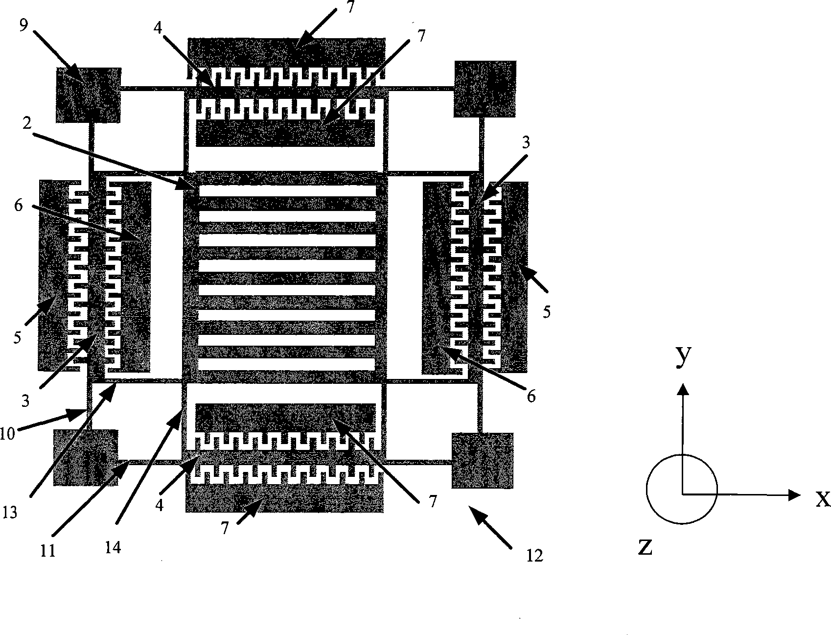
[0026] figure 1 It is a schematic diagram of the silicon structure of the micromechanical gyroscope of the preferred embodiment of the present invention. The silicon structure 12 includes:

[0027] A movable symmetrical grid-shaped central mass 2, which has a grid arranged along the y-axis direction, wherein the y-axis is the detection direction, and the x-axis perpendicular to it is the driving direction; the upper and lower sides of the central mass pass through The inner detection support beam 13 is connected to the drive comb structure 3, and its left and right sides are connected to the detection comb structure 4 through the inner drive support beam 14;

[0028] The driving comb structure 3 is symmetrically distributed on the left and right sides of the central mass, and is connected to the anchor points 9 located at the upper and lowe...


PUM


Abstract

The invention provides a decoupling micro-machine gyro, which comprises a glass substrate (1), a metal electrode (8) that covers the surface of the glass substrate (1), a movable central mass block (2) that is connected with a drive comb tooth structure (3) by an inside detection supporting beam (13) and with a detection comb tooth structure (4) by an inside drive supporting beam (14). The gyro is characterized in that the central mass block (2) and the metal electrode (8) are in a grate shape and therefore, when a capacitor with the detection comb tooth structure changes, a capacitor between the central mass block (2) and the metal electrode (8) also changes, thus causing the gyro to be capable of detecting the increased capacitance quantity at work and improving the sensitivity of the gyro.

Description

technical field [0001] The invention relates to an angular velocity sensor, in particular to a decoupling micromechanical gyroscope. Background technique [0002] Micromachined gyro is an angular velocity sensor developed on the basis of silicon micromachining technology, which uses Coriolis force to measure the rotational angular velocity of an object. Compared with traditional angular velocity sensors, micromechanical gyroscopes are smaller in size, lighter in weight, and lower in cost. At the same time, they also have many advantages such as high reliability, strong resistance to vibration and shock, mass production, and low price. Aerospace, robotic automatic control, inertial navigation, weapon guidance, automobiles, consumer electronics and other fields have very broad application prospects. [0003] When the micromechanical gyro is working, the mechanical coupling of the two modes of driving and detection will seriously affect the performance of the gyro. The solutio...

Claims


Application Information

Patent Timeline
Patent Type & Authority Applications(China)
IPC IPC(8): G01C19/56G01C19/5733
Inventor 张燕燕侯朝焕王东辉张铁军
Owner INST OF ACOUSTICS CHINESE ACAD OF SCI
Why Eureka
Try Eureka