Automobile digitalization instrument controlling and displaying method and device
A technology for controlling display and instruments, which is applied in the direction of measuring devices, electrical program control, sequence/logic controller program control, etc., can solve the problems that the driver cannot use the instrument, and the content of the display is small, so as to achieve accurate mileage display Reliable, accurate indication, powerful display
- Summary
- Abstract
- Description
- Claims
- Application Information
AI Technical Summary
Problems solved by technology
Method used
Image
Examples
Embodiment 1
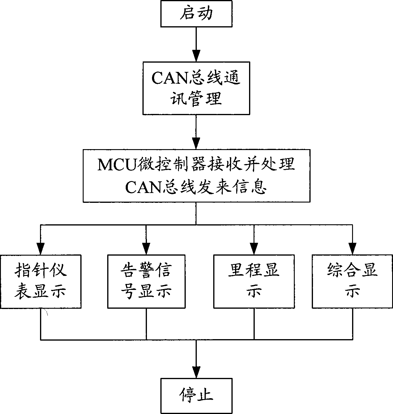
[0025] This embodiment is a method for controlling and displaying an automobile digital instrument, the process is as follows figure 1 shown. The instrument device used in the method includes: CAN bus, MCU microcontroller, pointer digital instrument driven by stepping motor, LED information indicator light, LCD digital display with selection button, LCD integrated display with operation bar . The process of the method is as figure 1 As shown, the operation steps are as follows:
[0026] In the step of starting, the instrument device is powered on for self-test, and whether it enters the state of low power consumption;
[0027] The steps of CAN bus communication management;
[0028] Steps for the MCU microcontroller to receive and process the information sent by the CAN bus;
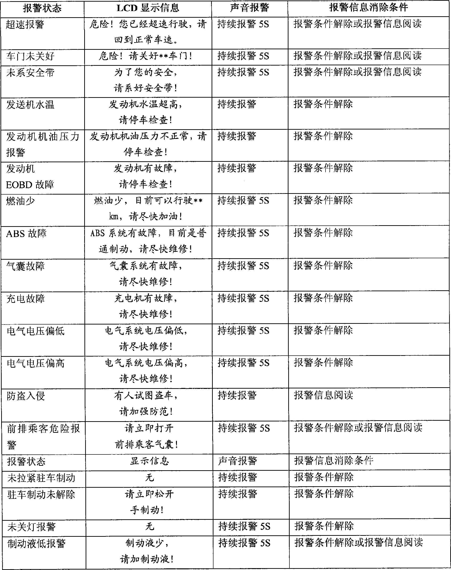
[0029] In the steps of pointer instrument display, the MCU microcontroller transmits the four signals of water temperature, oil quantity, engine speed, and vehicle speed to the digital pointer instru...
Embodiment 2
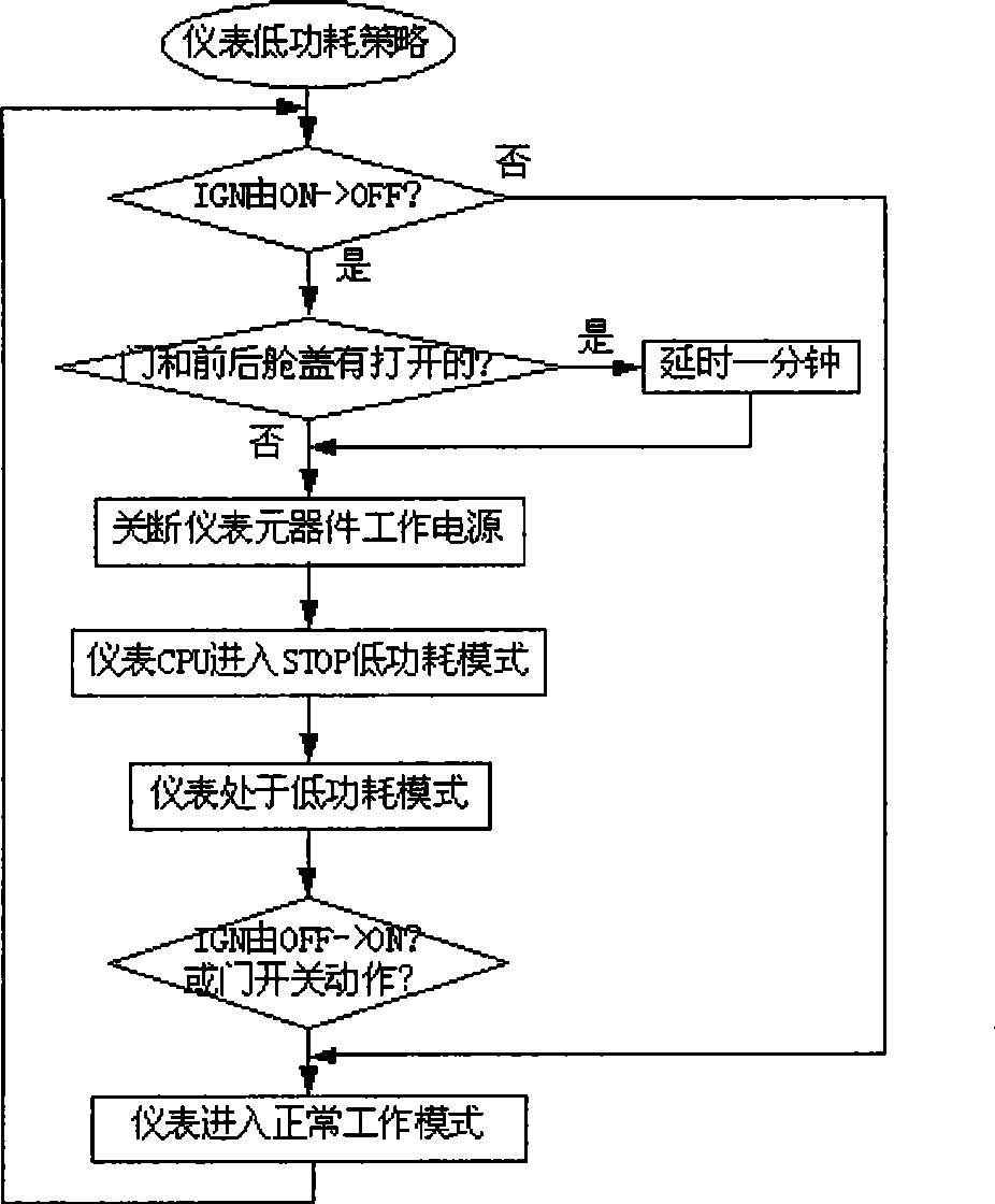
[0040] This embodiment is an improvement of the first embodiment, and is a refinement of the detection of whether to enter the low power consumption state in the step of starting in the control and display method of the automobile digital instrument described in the first embodiment. In order to ensure the low power consumption performance of the automobile digital instrument, this embodiment designs a system sleep wake-up function. When the instrument is not working, the system enters the dormant state, shuts off the power supply of the corresponding external chip, and the MCU enters the STOP mode to reduce the power consumption of the entire instrument. When the instrument is about to work, if the external relevant switch is activated, the instrument will be awakened and resumed to the working state. The above process as image 3 As shown, the sub-steps include:
[0041] The sub-step of judging whether the ignition switch is turned from on to off, if "yes" then enters the ...
Embodiment 3
[0048] This embodiment is an improvement of the second embodiment, and is a refinement of the CAN bus communication management steps described in the control and display method of the automobile digital instrument described in the second embodiment. The CAN communication function is an important feature of this embodiment. In order to ensure the normal progress of CAN communication, this embodiment designs a relatively comprehensive network management strategy for CAN communication.
[0049] After the ignition switch changes from OFF to ON and then from ON to OFF, it can effectively manage the start of CAN communication and the synchronous shutdown of the node network.
[0050] Under normal communication conditions, the frame timeout is effectively monitored and processed. Monitor and judge Bus Off, and restore CAN communication in time after Bus Off occurs.
[0051] Under normal working conditions, the system voltage can be monitored, and the start, stop and diagnosis of CAN...
PUM
 Abstract
Description
Claims
Application Information
 - R&D
- Intellectual Property
- Life Sciences
- Materials
- Tech Scout
- Unparalleled Data Quality
- Higher Quality Content
- 60% Fewer Hallucinations
Browse by: Latest US Patents, China's latest patents, Technical Efficacy Thesaurus, Application Domain, Technology Topic, Popular Technical Reports.
© 2025 PatSnap. All rights reserved.Legal|Privacy policy|Modern Slavery Act Transparency Statement|Sitemap|About US| Contact US: help@patsnap.com


