Direct current transmission line double-end asynchronous and parameter self-adapting fault distance measuring time-domain method

A DC transmission line, double-terminal asynchronous technology, applied in the direction of the fault location, etc., can solve the problems of subtle change errors in wave velocity, and cannot meet real-time environmental changes, etc.

Active Publication Date: 2009-08-19
SOUTH CHINA UNIV OF TECH +1
View PDF0 Cites 74 Cited by
  • Summary
  • Abstract
  • Description
  • Claims
  • Application Information

AI Technical Summary

Problems solved by technology

For the determination method of traveling wave velocity, the traveling wave velocity can be corrected with the help of historical fault data, ...

Method used


Image

  • Direct current transmission line double-end asynchronous and parameter self-adapting fault distance measuring time-domain method
  • Direct current transmission line double-end asynchronous and parameter self-adapting fault distance measuring time-domain method
  • Direct current transmission line double-end asynchronous and parameter self-adapting fault distance measuring time-domain method

Examples


Embodiment 1

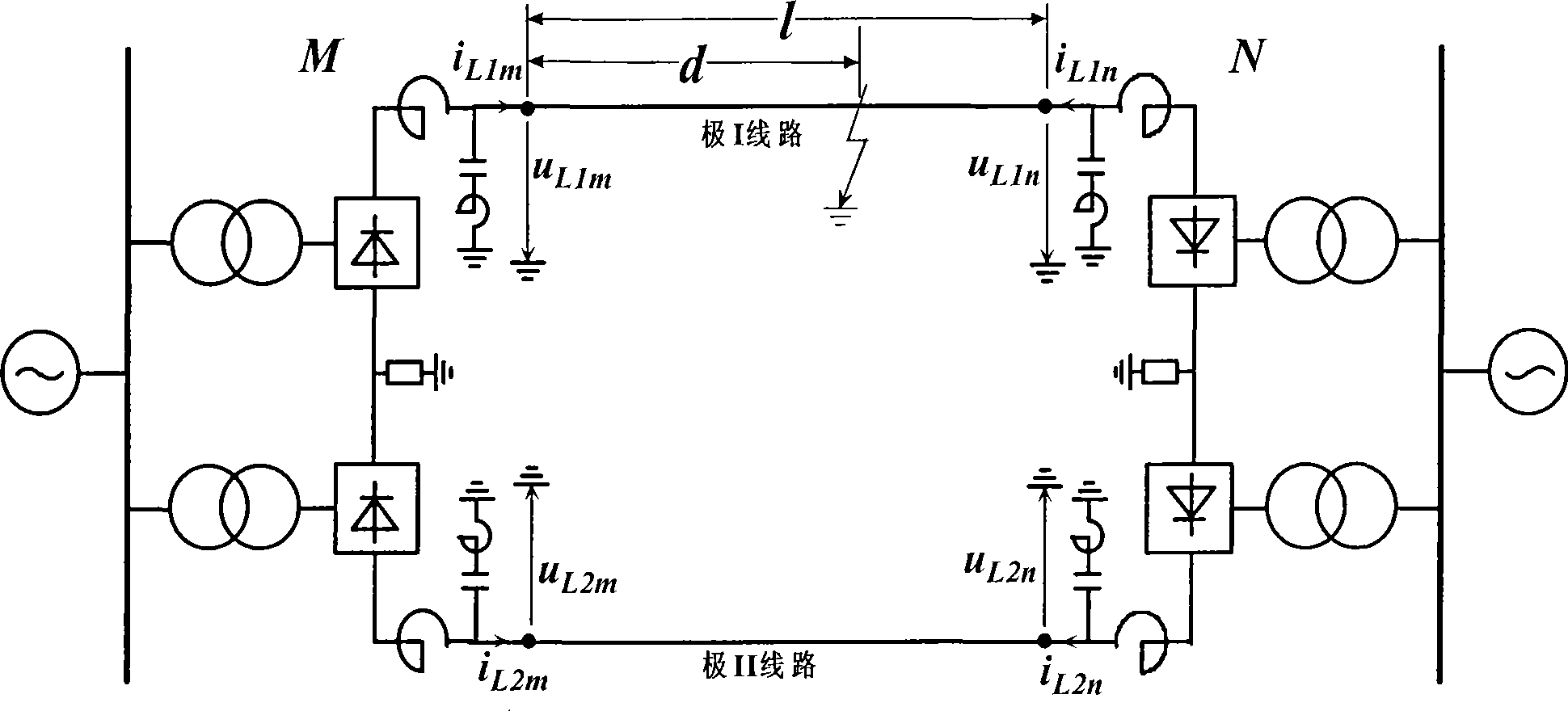
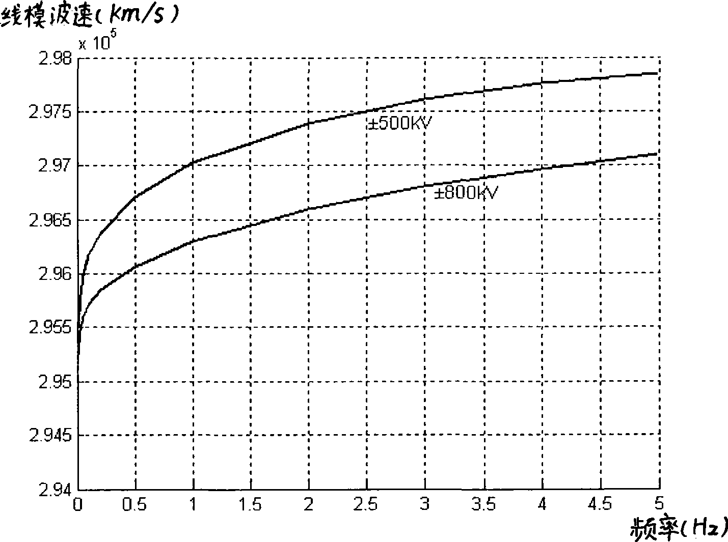
[0050] In this example, the ±500kV DC transmission system model is adopted, and the total length of the transmission line is 936km. The pole I line is the faulty transmission line, and the pole II line is the normal transmission line. The two ends of the transmission line are respectively set as M terminal and N end. At both ends of the transmission line, the fault traveling wave recording device is used to collect the voltage and current of the M terminal and the N terminal, and the data sampling frequency is 1MHz.

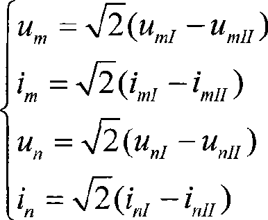
[0051] The first step is to convert the collected instantaneous voltage and current values ​​at terminals M and N of DC lines of pole I and pole II into line-mode voltage and current at both ends of M and N:

[0052] u m = 2 ( u ...

Embodiment 2

[0085] In this example, the ±800kV DC transmission system model is adopted, and the total length of the transmission line is 1438km. The pole I line is the faulty transmission line, and the pole II line is the normal transmission line. The two ends of the line are respectively set as the M terminal and the N terminal. . Both ends of the line adopt fault traveling wave recorder to collect the voltage and current of M terminal and N terminal, and the data sampling frequency is 1MHz.

[0086] The first step is to convert the collected instantaneous voltage and current values ​​at terminals M and N of DC lines of pole I and pole II into line-mode voltage and current at both ends of M and N:

[0087] u m = 2 ( u mI ...


PUM


Abstract

The invention discloses a time-domain failure distance measuring method with two asynchronous ends of a direct-current power line and self-adaptive parameters, which comprises the following steps of: setting up an asynchronous time-domain failure observation equation of the direct-current line, which includes quantities of fault distance, distributed resistances of the line, transmission wave velocity, wave impedance, asynchronous time difference of data at the two ends and the like to be observed; taking the time of initial failure traveling waves which arrive at the two ends of the line respectively as reference time of data at each end; introducing a traveling wave characteristic equation; and eliminating the quantities to be observed of asynchronous time difference in the time-domain failure observing equation, thus obtaining a novel time-domain failure distance measuring method of the direct-current line so as to realize self-adaption of the line parameter self-adapting without synchronizing with a clock. The time-domain failure distance measuring method has higher transition resistance durability and can effectively improve the accuracy and reliability of failure distance measurement at the two ends of the direct-current line.

Description

technical field [0001] The invention relates to a method for fault distance measurement of a direct current transmission line in a power system, in particular to a time-domain method for distance measurement of a double-terminal fault distance of a direct current transmission line that does not need a synchronous clock and whose parameters are self-adaptive in combination with traveling wave characteristics. Background technique [0002] The transmission distance of the DC transmission system is long, and the probability of line failure is high. Accurate distance measurement of line faults is of great significance for reducing the maintenance time of power outages and improving the reliability of the DC transmission system. At present, the fault location of DC transmission lines adopts the double-terminal traveling wave method, that is, the fault location is realized by detecting the exact moment when the initial line-mode voltage traveling wave of the fault reaches both ends...

Claims


Application Information

Patent Timeline
IPC IPC(8): G01R31/08
Inventor 王钢梁远升李海锋黄敏朱革兰黎小林傅闯
Owner SOUTH CHINA UNIV OF TECH
Why Eureka
Try Eureka