Composite phase mask plate

A technology of phase mask and phase distribution, which is applied in television, optics, instruments, etc., can solve the problem of system resolution reduction and achieve good application prospects, good suppression effect, and good depth-of-field expansion ability

Inactive Publication Date: 2009-08-19
ZHEJIANG UNIV
View PDF0 Cites 7 Cited by
  • Summary
  • Abstract
  • Description
  • Claims
  • Application Information

AI Technical Summary

Problems solved by technology

[0002] In traditional imaging systems, reducing the relative aperture is an effective way to expand the depth of fi

Method used


Image

  • Composite phase mask plate
  • Composite phase mask plate
  • Composite phase mask plate

Examples


Embodiment Construction

[0026] A composite phase mask, the phase distribution function of the composite phase mask includes both sinusoidal and exponential functions, and the function of the phase distribution function θ (x, y) is as follows:

[0027] θ ( x , y ) = α · x · [ exp ( βx 2 + exp ( β y 2 ) ] + 1 2 α [ sin ( ωx ) + sin ( ωy ...


PUM


Abstract

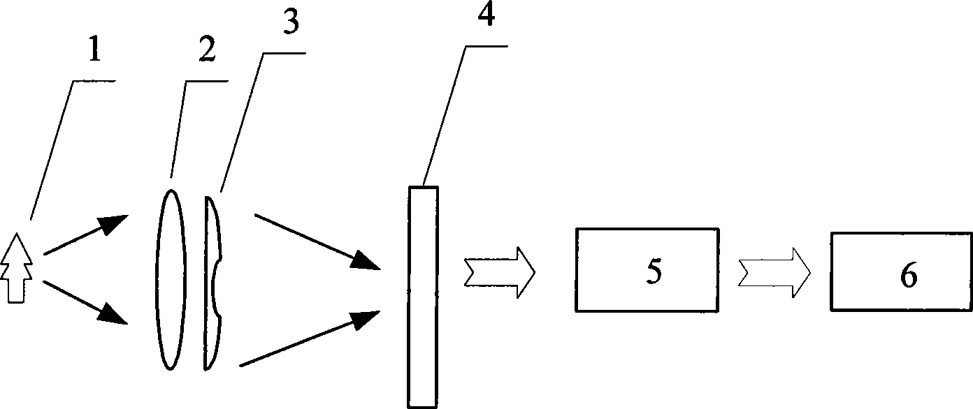
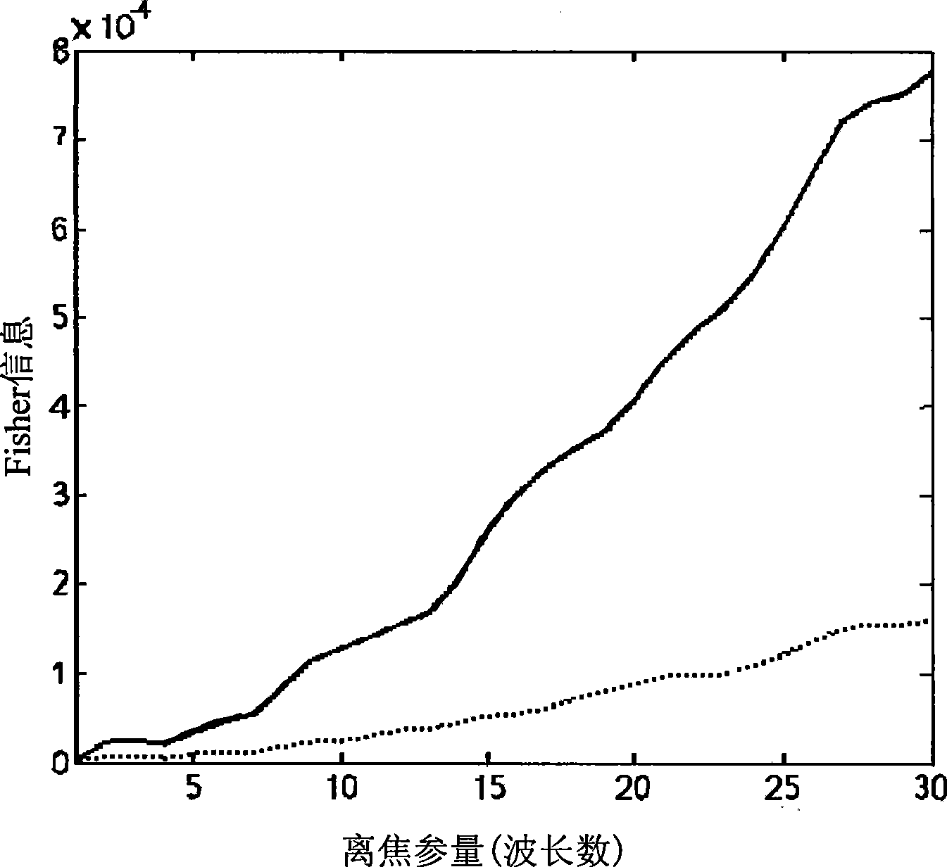
The invention discloses a composite phase mask, the phase distribution function of which contains two different functions, namely, a sinusoidal type function and an exponential type function. The function expression of the phase distribution function Theta(x, y) is as follows: Theta(x, y) is equal to Alpha question mark x question mark (Epsilon x Rho(Beta x plus Epsilon x Rho(Beta y)) plus (1/2)Alpha(sin(Omega x) plus sin(Omega y)), and in the expression, Omega question mark x question mark (Epsilon x Rho(Beta x plus Epsilon x Rho(Beta y)) is an exponential type function, and (1/2)Alpha(sin(Omega x) plus sin(Omega y)) is a sinusoidal type function; wherein Alpha expresses the amplitudes of the exponential type function and the sinusoidal type function, Beta expresses the modulation factor of the exponential type function, Omega expresses the angular frequency of the sinusoidal type function, and x, y is space coordinate with normalized aperture plane. The invention also discloses an imaging system which adopts the composite phase mask compounded by the sinusoidal type function and the exponential type function; and the imaging system has smaller numerical value of the Fisher information, is not sensitive to defocusing, has better inhibiting effect on defocusing amount and has better expansion capability of depth of focus.

Description

technical field [0001] The invention relates to a phase mask, in particular to a composite phase mask in which sinusoidal and exponential functions are compounded. Background technique [0002] In traditional imaging systems, reducing the relative aperture is an effective way to expand the depth of field, but this will lead to a decrease in system resolution, which is contrary to the purpose of high-quality imaging. Therefore, the new imaging method represented by wavefront coding has become a research hotspot. Using wavefront coding technology to make a mask plate equivalent to an aspheric surface, the object target forms a blurred intermediate image that is not sensitive to defocus after passing through the optical system with a mask plate, and then performs digital image processing on the intermediate image Finally, a clearly focused image can be obtained. This method can make the modulation transfer function value of the optical system change very little in a large defo...

Claims


Application Information

Patent Timeline
IPC IPC(8): G02B27/46H04N5/225
Inventor 李奇赵惠冯华君徐之海
Owner ZHEJIANG UNIV
Why Eureka
Try Eureka