Massage device

A technology for the treatment of parts and joints, applied in the directions of kneading massage equipment, massage aids, physical therapy, etc., which can solve the problem that the frame surface does not conform to the shape and curve of the body

Active Publication Date: 2009-08-19
PANASONIC CORP
View PDF1 Cites 5 Cited by
  • Summary
  • Abstract
  • Description
  • Claims
  • Application Information

AI Technical Summary

Problems solved by technology

[0003] On the other hand, when massaging the user, the most reasonable control is to control the position along the curve of the body shape, and to control the force in the depth direction of the curve of the body shape. Controls have room for improvement

Method used


Image

  • Massage device
  • Massage device
  • Massage device

Examples


Embodiment Construction

[0028] Hereinafter, the present invention will be described in detail using the drawings. In the massage machine of the present invention, a treatment section is arranged on the top of a massage mechanism consisting of at least 3 or more joints, such as Figure 11 As shown, the above-mentioned massage mechanism is installed in the frame that constitutes the yz plane. As a massage machine equipped with such a massage mechanism, for example, a massage machine having a structure shown in JP 2006-34635 A can be suitably used, but the present invention is not limited thereto.

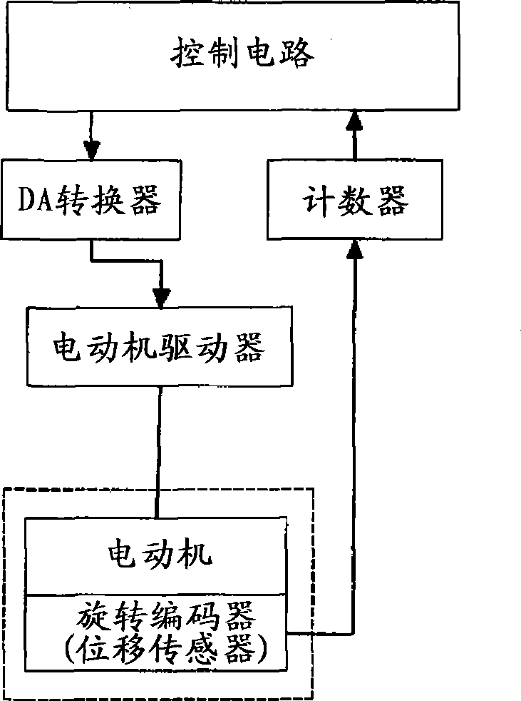
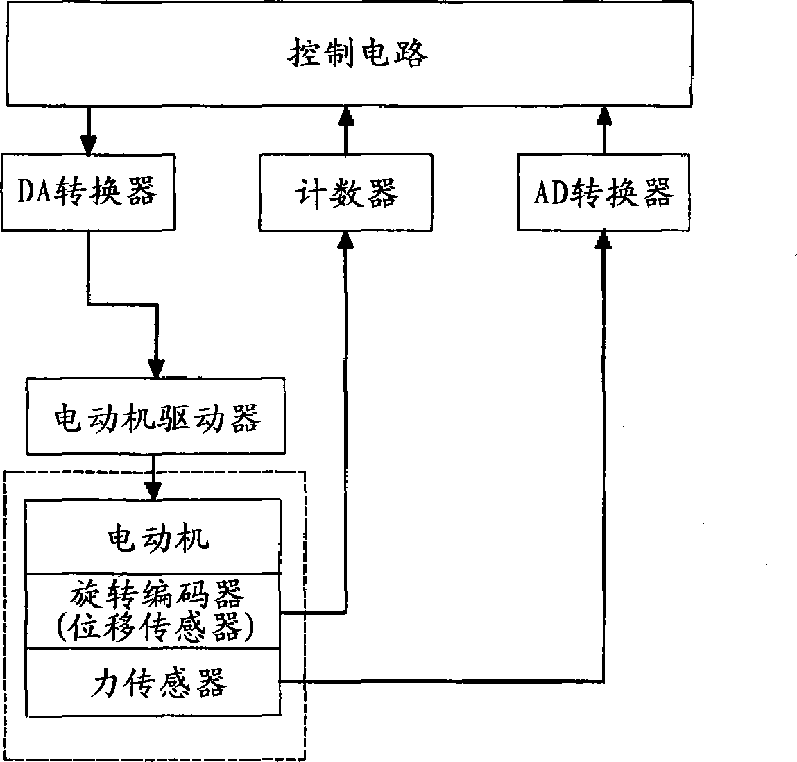
[0029] The above-mentioned joints, such as figure 1 As shown, the motor is installed as the actuator, and the rotor rotary encoder is installed as the displacement sensor for displacement detection. According to the value input by the rotary encoder through the counter, the control circuit (control part) determines the motor command value, and the DA converter and the motor The driver drives the motor. At...


PUM


Abstract

The invention relates to a device and a method wherein tunable transmitters (1.1) and detectors (receivers) (1.2) are integrated into a non-linear detection system (1) and a narrow-band signal having a variable frequency (f1) is used. The scannable frequency range should be between 10 - 1000 MHz. The frequency acceptance range for the second (f2) and third (f3) harmonic is adjusted according to the transmit frequency (f1).

Description

technical field [0001] The invention relates to a massage machine, in particular to a massage machine with a massage mechanism arranged in the back of a chair. Background technique [0002] Conventionally, there have been provided various massage machines in which a massage mechanism is arranged in the back of a chair (for example, Japanese Patent No. 2733159). In these inventions, the massage mechanism is installed in a fixed frame, and the force control is carried out in the direction perpendicular to the frame surface, and the position control is carried out in the surface direction. [0003] On the other hand, when massaging the user, the most reasonable control is to control the position along the curve of the body shape, and to control the force in the depth direction of the curve of the body shape. Controls have room for improvement. Contents of the invention [0004] The present invention was made in view of the above-mentioned conventional problems, and its obje...

Claims


Application Information

Patent Timeline
Patent Type & Authority Applications(China)
IPC IPC(8): A61H7/00
CPCA61H7/00A61H2201/5064A61H2201/5025A61H2201/0149A61H2201/5061A61H2201/5069
Inventor 谷口祥平
Owner PANASONIC CORP
Why Eureka
Try Eureka