Furniture hinge

A technology for hinges and furniture, applied to hinges with pins, door/window accessories, wing leaf parts, etc., can solve problems such as difficult assembly and coupling troubles, and achieve the effect of simple structure

Active Publication Date: 2014-07-02
HETTICH ONI
View PDF8 Cites 0 Cited by
  • Summary
  • Abstract
  • Description
  • Claims
  • Application Information

AI Technical Summary

Problems solved by technology

Additionally, coupling via chain links

Method used


Image

  • Furniture hinge
  • Furniture hinge

Examples


Embodiment Construction

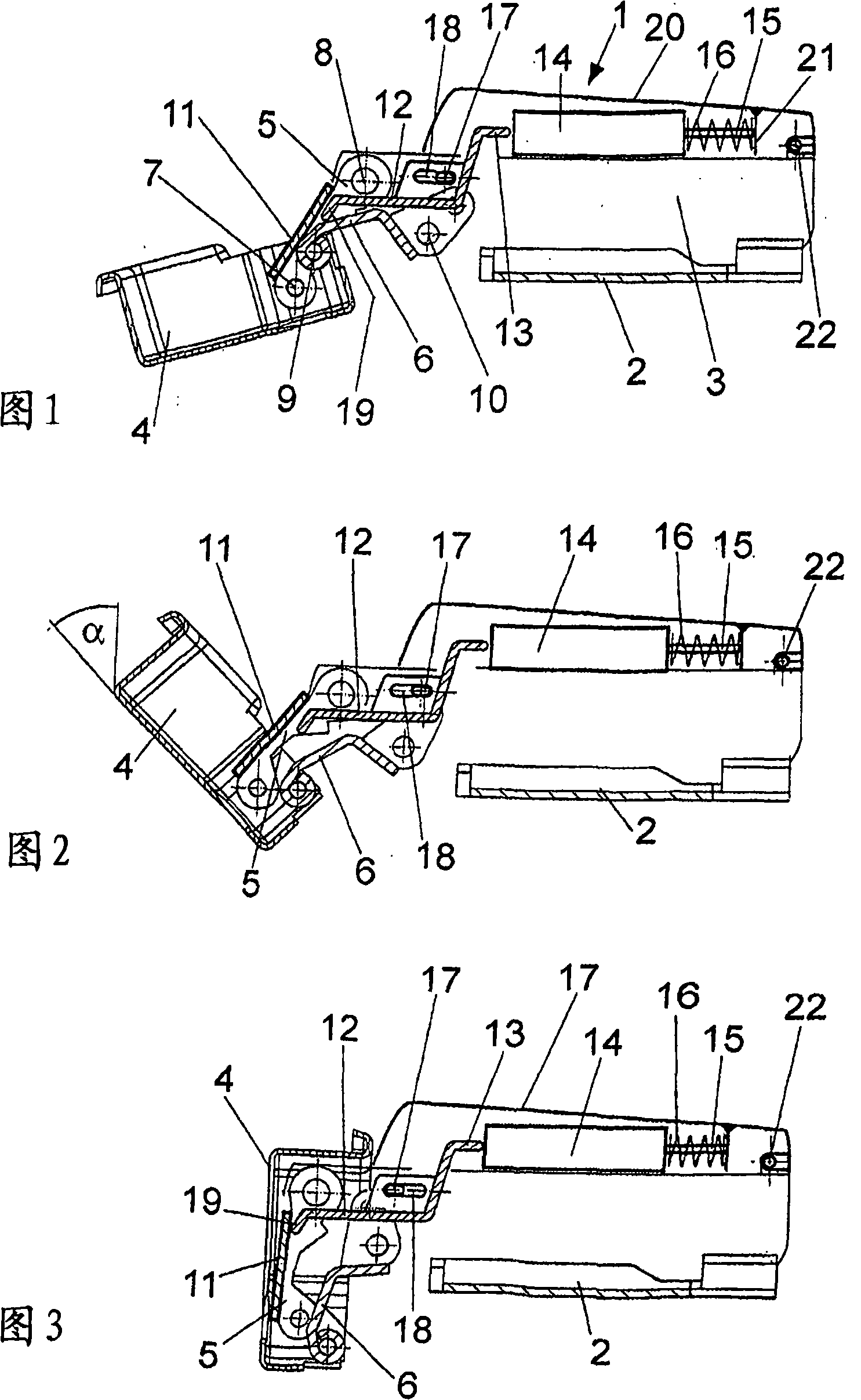
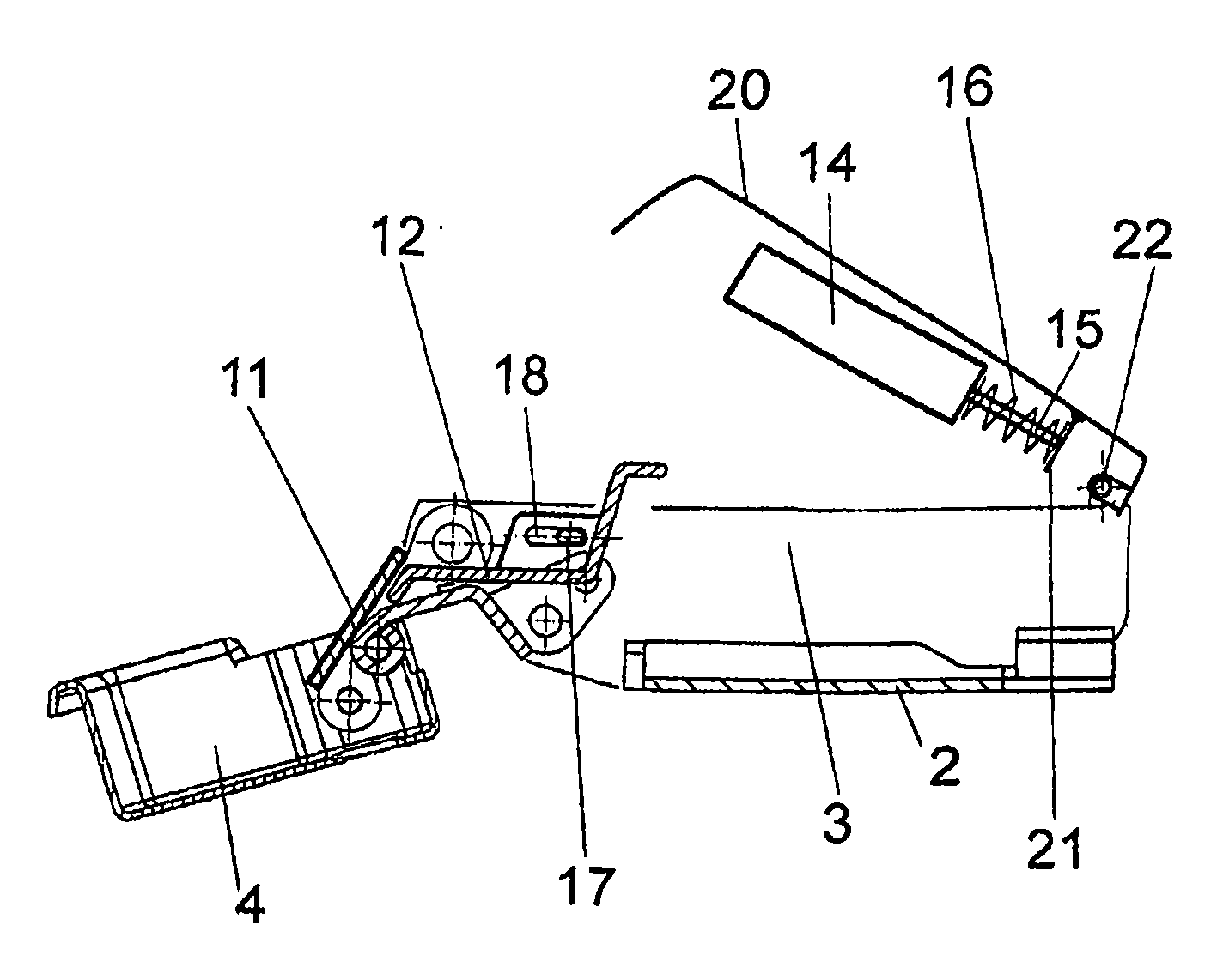
[0018] The furniture hinge 1 made of metal and / or plastic comprises a mounting plate 2 which can be fastened to the furniture body, on which a side part 3 is fixedly or adjustable. A pot-shaped hinge part 4 is pivotably mounted on the side part 3 , wherein a support rod 5 and a guide rod 6 are provided for the pivoting movement. The support rod 5 is hinged to the hinge member 4 via a shaft 7 and hinged to the side member 3 via a shaft 8 . The guide rod 6 is rotatably mounted on the hinge part 4 via a shaft 9 and is rotatably mounted on the side part 3 via a shaft 10 . The hinge part 4 can be fixed on the groove of a furniture door.

[0019] A bar 11 is integrally formed on the support rod 5 and can come into contact with a bent tip 19 of a linearly movable slide 12 . In this case, the slide 12 is supported on the side part 3 via guides. For this purpose, an elongated hole 18 is provided on the slide 12 , in which a pin 17 fastened to the side part 3 is inserted.

[0020] O...


PUM


Abstract

A furniture hinge (1), comprising a mounting plate (2), on which a side part (3) is arranged; and a hinge part (4), which is connected via a support rod (11) and a guide rod (6) ) is rotatably supported on the side part (3), wherein a damper (14, 15) is provided for damping the movement of the hinge part (4) relative to the side part (3). A slide plate (12) is also installed on the side part (3), which abuts against a contact surface on the buffer (14, 15) and is established between the buffer (14, 15) and the support rod (11) , the coupling between the guide rod (6) or the hinge part (4). Wherein, the slide plate (12) constitutes a movable intermediate link, which is not fixedly assembled with the buffer through shaft connection, so tolerance compensation can be realized.

Description

technical field [0001] The invention relates to a furniture hinge, comprising a mounting plate, on which a side part is arranged; and a hinge part, which is rotatably supported on the side part via a support rod and a guide rod, wherein, in order to dampen the hinge A damper is provided for the movement of the part relative to the side part. Background technique [0002] A furniture hinge is known from EP1555372, in which a hinge part is mounted pivotably on a side part. For this purpose, a support rod and a guide rod are provided, which deflect, in the manner of a parallel control rod, a hinge part fixed to the movable furniture part, for example a furniture door. To dampen the movement, a linear damper is arranged on the side part, which is connected via a chain link to a projection on the guide rod. A damping effect is thus achieved when the guide rod is deflected. In this case, the coupling is designed to be rigid, so that limited tolerance compensation is possible, i...

Claims


Application Information

Patent Timeline
IPC IPC(8): E05D11/10
CPCE05F5/006E05D11/1021E05Y2201/21E05Y2201/626E05Y2900/20E05D11/0054E05Y2201/256E05Y2201/264E05Y2600/45E05D3/06E05D11/10E05F5/02
Inventor W·贝克曼K-M·施图克O·舍尔R·米特尔蒂斯M·舒伯特J·克勒夫曼
Owner HETTICH ONI
Why Eureka
Try Eureka