Unlock instant, AI-driven research and patent intelligence for your innovation.

Variable displacement compressor

A compressor and capacity technology, applied in the direction of liquid variable capacity machinery, mechanical equipment, machines/engines, etc., can solve problems such as large sliding resistance

Inactive Publication Date: 2009-08-19
CALSONIC KANSEI CORP
View PDF1 Cites 4 Cited by
  • Summary
  • Abstract
  • Description
  • Claims
  • Application Information

AI Technical Summary

Problems solved by technology

In this way, when changing the inclination angle of the swash plate 101, the sliding resistance between the two 102, 104 is extremely large.

Method used


Image

  • Variable displacement compressor
  • Variable displacement compressor
  • Variable displacement compressor

Examples


Embodiment Construction

[0021] Next, a variable displacement compressor and a hinge mechanism used therein according to an embodiment of the present invention will be described with reference to the drawings.

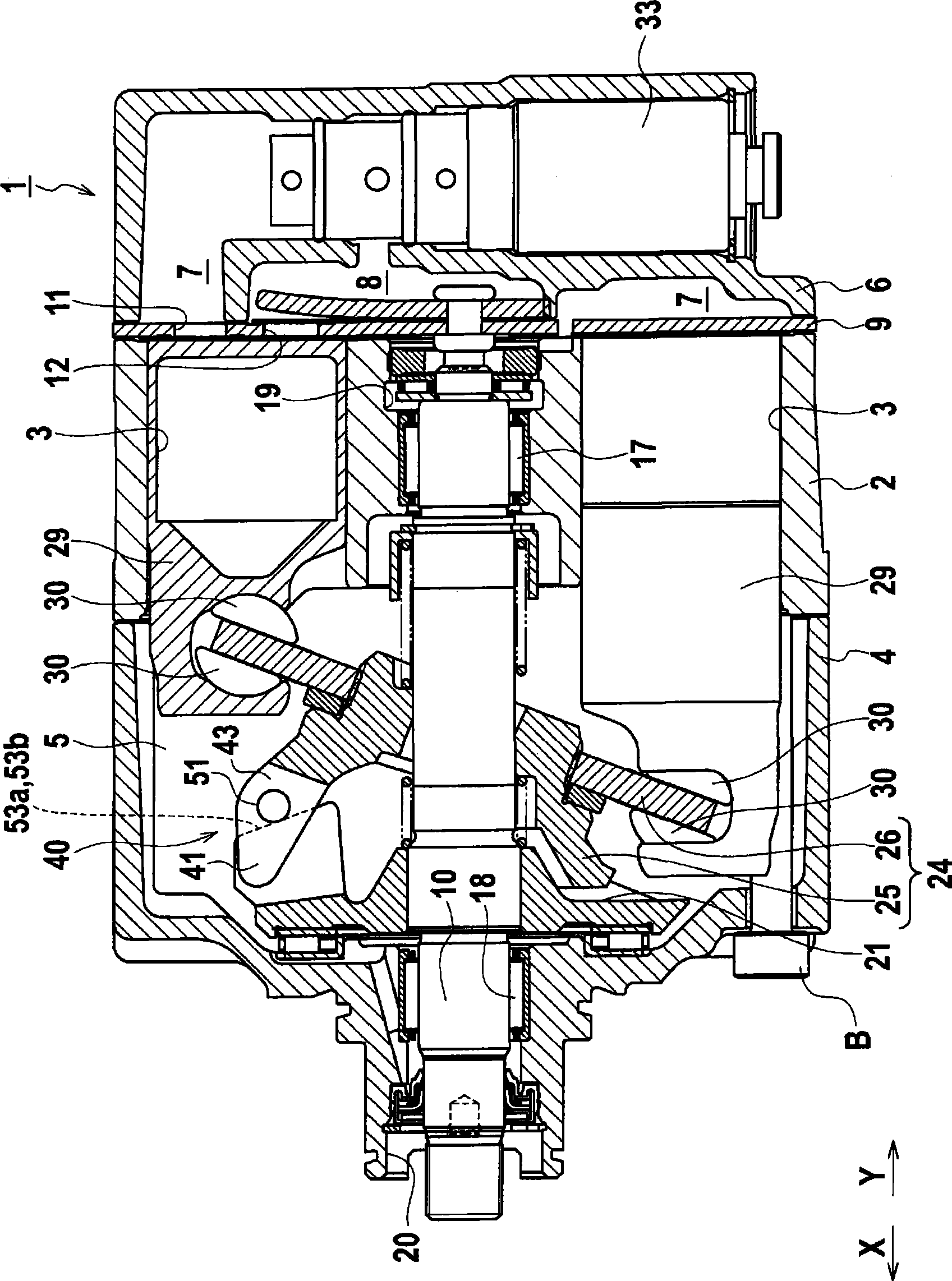
[0022] First, refer to figure 1 , 2 The outline of the variable capacity compressor of this embodiment is demonstrated. figure 1 is the state representing the maximum stroke, figure 2 It indicates the state of the minimum stroke.

[0023] Such as figure 1 , 2 As shown, the variable capacity compressor 1 includes a cylinder block 2, a front casing 4 and a rear casing 6; the above-mentioned cylinder block 2 has a plurality (six in this example) of cylinders arranged at equal intervals in the circumferential direction cylinder 3; the above-mentioned front housing 4 is connected to the front end surface of the cylinder block 2, and a crank chamber 5 is formed inside; the above-mentioned rear housing 6 is connected to the rear end surface of the cylinder block 2 through a valve plate 9, an...


PUM


Abstract

A hinge mechanism (40) of a variable capacity compressor (1) includes an arm (41) protruded toward a tilting member (24) from a rotation member (21), an arm (43) protruded toward the rotation member (21) from the tilting member (24) to receive a rotational torque from the arm (41) of the rotation member, a pin (51) fixed to one of the arm (41) of the rotation member and the arm (43) of the tilting member, and an axial-load receiving surface (53a, 53b) formed on the other of the arm (41) of the rotation member and the arm (43) of the tilting member and configured to be in contact with the pin (51) so as to receive an axial load produced between the rotation member (21) and the tilting member (24). A position where the pin (51) and the axial-load receiving surface (53a) contact with each other when the swash plate (24) has a maximum inclination angle is located within a range of 27 to 90 degrees anterior, in the rotational direction, to a position (TDC) corresponding to the top dead center.

Description

technical field [0001] The present invention relates to a variable capacity compressor having a hinge mechanism capable of relative rotational movement while transmitting torque. Background technique [0002] For example, JP 2004-068756 A discloses a conventional variable capacity compressor. Such as Figure 11 ~ Figure 13 As shown, the variable capacity compressor includes: a drive shaft 105; a rotor 103 fixed on the drive shaft 105 and rotating integrally with the drive shaft; a swash plate 101 (cam plate) slidably mounted on the drive shaft 105; The unillustrated piston is locked on the swash plate 101 and is housed in the unillustrated cylinder so as to reciprocate freely. By changing the inclination angle of the swash plate 101, the stroke of the piston can be changed, thereby changing the discharge capacity. . Since the inclination angle of the swash plate is changed while torque is transmitted from the rotor 103 to the swash plate 101 , a hinge mechanism is provided...

Claims


Application Information

Patent Timeline
IPC IPC(8): F04B27/08
CPCF04B27/1072F04B25/04F04B27/08
Inventor 牧岛弘幸小林伸之
Owner CALSONIC KANSEI CORP
Features
  • R&D
  • Intellectual Property
  • Life Sciences
  • Materials
  • Tech Scout
  • Unparalleled Data Quality
  • Higher Quality Content
  • 60% Fewer Hallucinations
Learn More