
Automatic transmission controlling apparatus and method

A technology of automatic transmission and control device, applied in the direction of transmission control, components with teeth, belt/chain/gear, etc., which can solve the problems of speed change shock, lengthening of speed change action period, and inability to detect rotational speed of rotating elements, etc. Achieve the effect of suppressing shifting shock and improving responsiveness

Inactive Publication Date: 2012-11-14
TOYOTA JIDOSHA KK
View PDF5 Cites 0 Cited by
  • Summary
  • Abstract
  • Description
  • Claims
  • Application Information

AI Technical Summary

Problems solved by technology

That is, after the intermediate gear stage is completely formed by switching from the first friction element to the fourth friction element, the switching from the second friction element to the third friction element may be performed, so the period of the shifting operation may become longer.
[0007] In addition, when the first friction element and the second friction element are replaced in parallel, from the time the first friction element and the second friction element are released until the third friction element and the fourth friction element are engaged, in the automatic transmission, there is There are rotating elements that cannot detect the rotational speed, so there may be a shift shock when the third friction element and the fourth friction element are engaged

Method used


Image

  • Automatic transmission controlling apparatus and method
  • Automatic transmission controlling apparatus and method
  • Automatic transmission controlling apparatus and method

Examples


no. 1 example

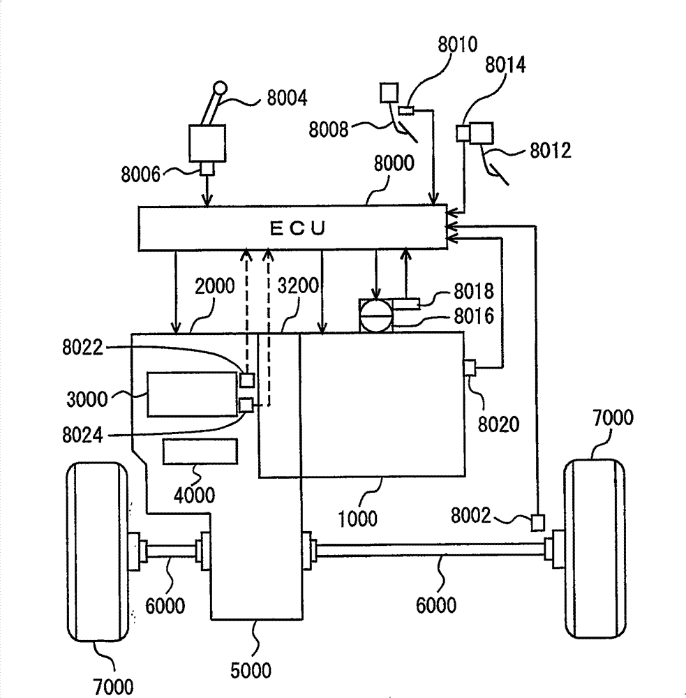
[0045] refer to figure 1 A vehicle equipped with a control device according to an embodiment of the present invention will be described. This vehicle is an FF (Front engine Front drive) vehicle. Vehicles other than FF may also be used.

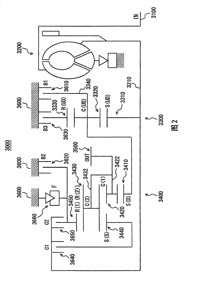
[0046] The vehicle includes an engine 1000, an automatic transmission 2000, a planetary gear unit 3000 constituting a part of the automatic transmission 2000, a hydraulic circuit 4000 constituting a part of the automatic transmission 2000, a differential gear 5000, a drive shaft 6000, front wheels 7000, an ECU (Electronic Control Unit )8000. The control device of the automatic transmission of the present invention is realized by ECU8000.

[0047] Engine 1000 is an internal combustion engine that combusts a mixture of fuel and air injected from an injector (not shown) in a combustion chamber of a cylinder. Combustion depresses the piston in the cylinder and rotates the crankshaft.

[0048] Automatic transmission 2000 is connected to engine...


PUM


Abstract

An ECU executes a program including a step (S102) of starting monitoring of the rotational speed of the turbine and the rotational speed of output shaft when direct gear change is started (YES at step S100), a step (S106) of making a control of completely releasing a release element (1), a step (S110) of lowering the control pressure of the release element (2) to a predetermined control pressure,a step (S114) of starting engagement control of an engagement element (1) when a set time Ts (1) elapses (YES at step S112), and a step (S120) of making a control of completely releasing the release element (2) when a set time Ts (2) elapses (YES at step S118), and a step (S124) of starting engagement control of the engagement element (2) if the rotational speed NT of the turbine is a value equalto or more than the remainder of the subtraction, after-gear-change gear position synchronous rotational speed - set value Ns (YES at step S122).

Description

technical field [0001] The present invention relates to control of an automatic transmission, and in particular to control of a speed change that requires replacement of two or more frictional engagement elements in a short time while suppressing a shift shock. Background technique [0002] The components of the automatic transmission of a vehicle include planetary gears and friction engagement elements, which are composed of rotating elements such as sun gears, ring gears, and planetary gears. In such an automatic transmission, any one of a plurality of gear stages is formed by switching a combination of engaged frictional engagement elements to switch a transmission path of torque transmitted from an engine. In particular, in an automatic transmission with a large number of gear stages (for example, a 6-speed automatic transmission), a plurality of clutch elements as input elements and brake elements as counterforce elements are respectively provided. [0003] In such an ...

Claims


Application Information

Patent Timeline
Patent Type & Authority Patents(China)
IPC IPC(8): F16H61/08F16H59/40F16H59/42F16H61/686
CPCF16H61/686F16H61/08F16H61/061Y10T74/19163
Inventor 福代英司太田圭祐大岛康嗣
Owner TOYOTA JIDOSHA KK
Learn More