Indoor unit of air conditioner

A technology for indoor units and air conditioners, applied in air conditioning systems, noise suppression, airflow control components, etc., can solve problems such as user inconvenience, and achieve the effects of reducing noise, optimizing suction/discharge structure, and increasing suction and discharge flow rates

Inactive Publication Date: 2009-08-19
LG ELECTRONICS INC
View PDF1 Cites 19 Cited by
  • Summary
  • Abstract
  • Description
  • Claims
  • Application Information

AI Technical Summary

Problems solved by technology

[0009] The rear side air suction structure has a filter installed on the rear side for this purpose, and it is necessary to drag the filter down from the rear side for cleaning, and to put the filter on the rear side after cleaning, which is very difficult for the user Not convenient

Method used


Image

  • Indoor unit of air conditioner
  • Indoor unit of air conditioner
  • Indoor unit of air conditioner

Examples


Embodiment Construction

[0045] Reference will now be made in detail to the preferred embodiments of the invention, examples of which are illustrated in the accompanying drawings.

[0046] The following will refer to Figures 1 to 17 An indoor unit according to a first preferred embodiment of the present invention will be described.

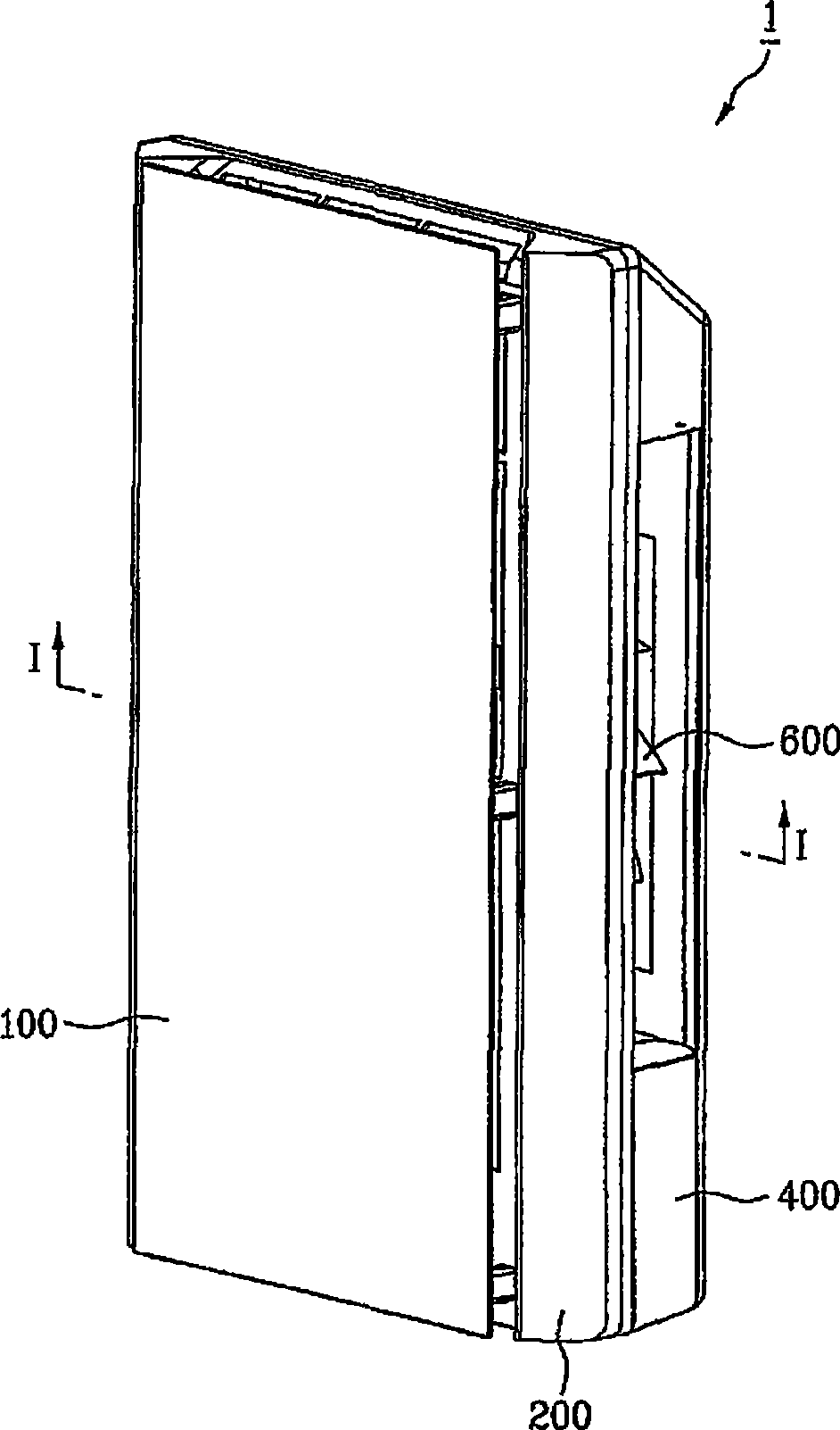
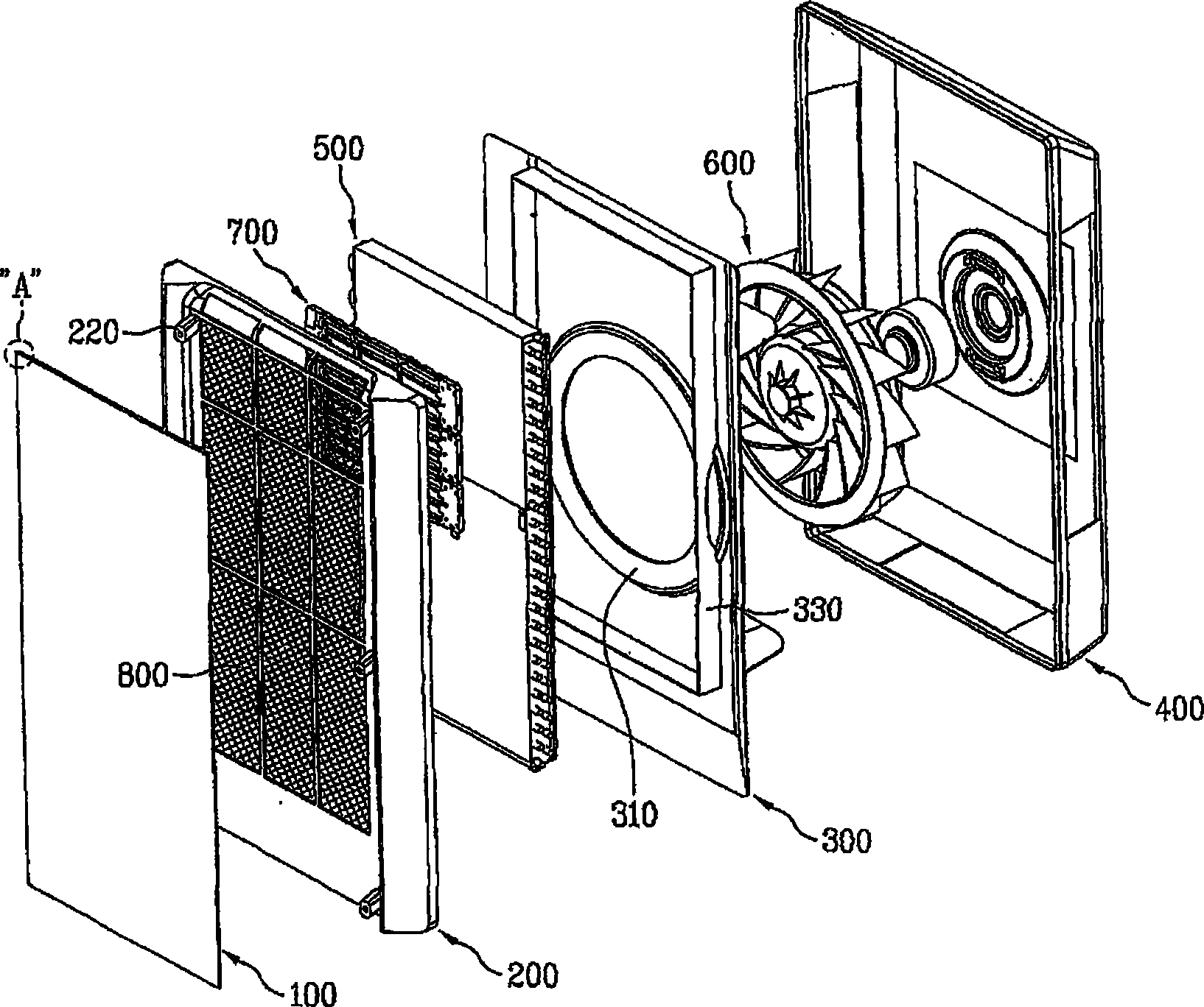
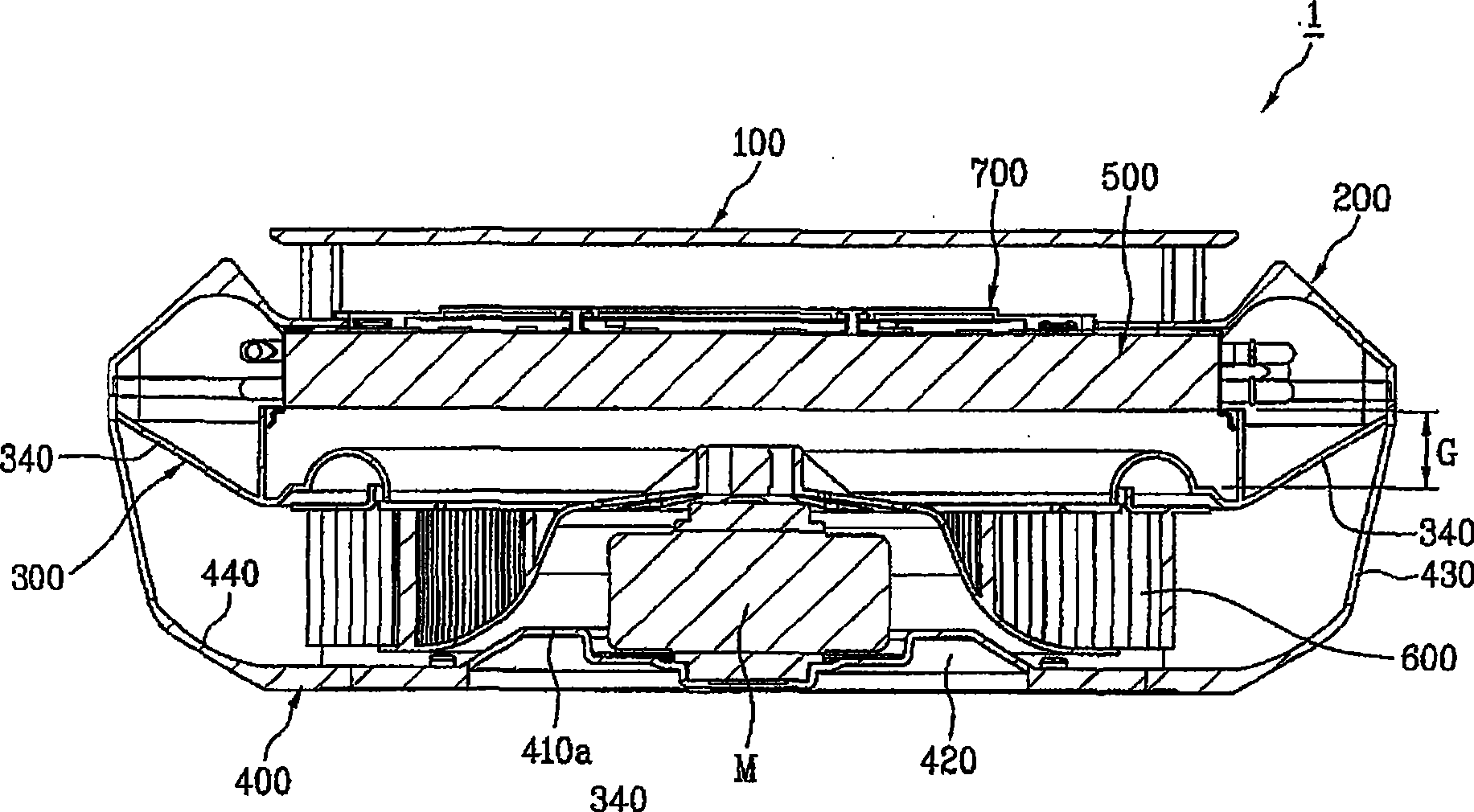
[0047] figure 1 An external perspective view showing an indoor unit according to a preferred embodiment of the present invention; figure 2 show figure 1 exploded perspective view of ; and image 3 showing along figure 1 Cross-sectional view of the indoor unit on line I-I.

[0048] Figure 4 show figure 2 A plan view of part "A" in for showing the edge structure of the front panel of the indoor unit of the present invention; and Figure 5 A perspective view showing the front frame of the indoor unit of the present invention.

[0049] Image 6 A perspective view showing the guide frame of the indoor unit of the present invention; Figure 7 show Image 6 front...


PUM


Abstract

Indoor unit which draws air through a front, and discharges air heat exchanged therein in a front direction through sides, having an optimized stricture with increased suction and discharge rates and low noise. For this, the indoor unit includes a front frame made to enable air suction through a front thereof, a base frame joined with the front frame, having outlets in sides and a bottom, and a motor seat for mounting a fan driving motor thereon, a guide frame between the front frame and the base frame for guiding an airflow, a heat exchanger between the front frame and the guide frame, a fan for discharging heat exchanged air to an outside of the indoor unit, and a front panel mounted in front of the front frame with a space thereto.

Description

technical field [0001] The present invention relates to an air conditioner, and more particularly, to an indoor unit that sucks in air through the front and discharges the air that has undergone heat exchange therein forward through the side, the indoor unit having a suction rate of And an optimized structure with increased discharge rate and low noise. Background technique [0002] Generally, an air conditioner repeats a refrigeration cycle in which a refrigerant is compressed, condensed, expanded, and evaporated. [0003] That is, the gaseous refrigerant at low temperature and low pressure before being introduced into the compressor is compressed into high temperature and high pressure gaseous refrigerant at the compressor, converted into high pressure liquid refrigerant at the condenser due to the discharge heat of the gaseous refrigerant, and As the high-pressure liquid refrigerant passes through the expansion valve, it is transformed into a low-temperature and low-pres...

Claims


Application Information

Patent Timeline
Patent Type & Authority Applications(China)
IPC IPC(8): F24F1/00F24F13/20F24F13/24F24F13/00F24F13/08
CPCF24F1/0014F24F1/0025F24F1/0033F24F13/08F24F13/20F24F13/24F24F13/30F24F2013/205F24F2221/17F24F1/0057F24F1/0063
Inventor 金正勋宋惠映金世睍洪宁基
Owner LG ELECTRONICS INC
Why Eureka
Try Eureka