
Apparatus for measuring the volume or mass flow of a medium in a pipeline

A technology for measuring pipelines and volume flow, applied in the direction of measuring flow/mass flow, volume/mass flow generated by electromagnetic effects, measuring devices, etc., can solve the problems of relatively expensive and high manufacturing costs of magnetic induction flowmeters, and achieve high corrosion resistance Effect

Inactive Publication Date: 2011-02-23
ENDRESS HAUSER FLOWTEC AG
View PDF1 Cites 0 Cited by
  • Summary
  • Abstract
  • Description
  • Claims
  • Application Information

AI Technical Summary

Problems solved by technology

However, if the medium to be measured or monitored is a corrosive medium, the metal from which the grounding disc is made must be chemically inert
A metal suitable for this is for example tantalum, which has a known disadvantage, namely that it is relatively expensive
If a grounded disc made of tantalum is used in a range with a large diameter, the manufacturing cost of the magnetic induction flowmeter will be very high

Method used


Image

  • Apparatus for measuring the volume or mass flow of a medium in a pipeline
  • Apparatus for measuring the volume or mass flow of a medium in a pipeline
  • Apparatus for measuring the volume or mass flow of a medium in a pipeline

Examples


Embodiment Construction

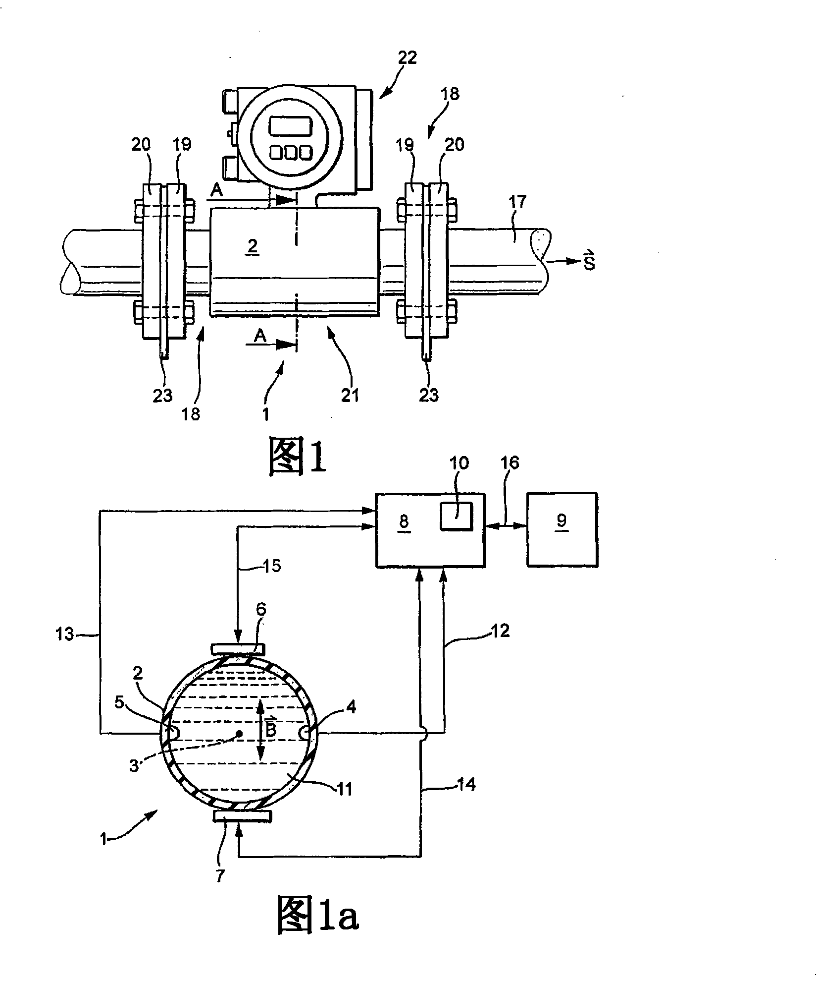
[0019] figure 1 is a plan view of one embodiment of the device 1 of the present invention. The flow meter 1 installed in the pipe 17 is composed of a sensor 21 and a transmitter 22 . Sensitive electronic components such as the control / evaluation unit 8 are arranged in the transmitter 22 .

[0020] A measuring tube flange 19 is fastened in each of the two end regions 18 of the measuring tube 2 of the flow meter 1 . Either the measuring tube flange 19 is welded to the measuring tube 2 ; or the measuring tube flange 19 is a loose flange which is pushed onto the measuring tube 2 with play and passes through the measuring tube 2 in the installed state of the flowmeter 1 The crimped end region 18 is fixed axially on the measuring tube 2 .

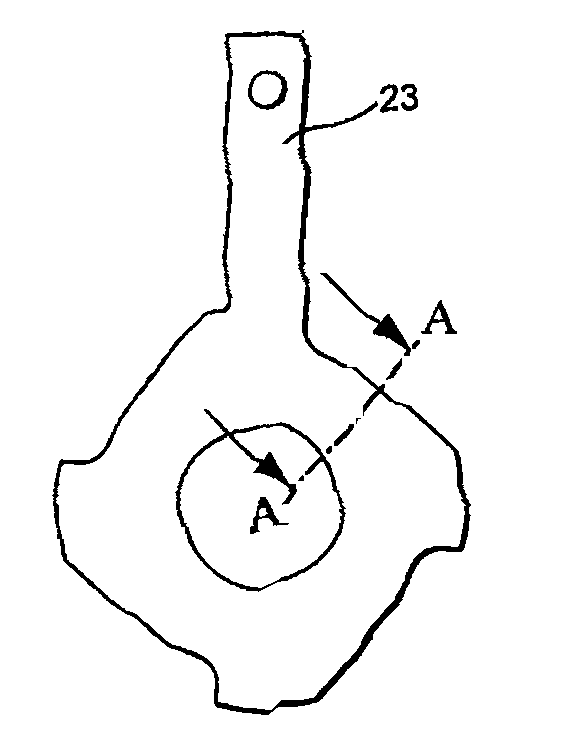
[0021] Two pipe flanges 20 are mounted on the two end regions of the pipe 17 between which the flow meter 1 is located. Between the measuring tube flange 19 and the pipe flange 20 an inventive ground disc 23 is provided. In addition to the e...


PUM


Abstract

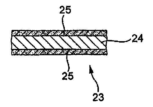
In order to put a medium which flows through a magnetic-inductive flowmeter (1) at a reference potential, in each case one grounding disc (23) is arranged between the angled end regions (18) of the measuring tube (2) or the measuring-tube flanges (19) mounted on the measuring tube (2) and the pipeline flanges (20) connected to the pipeline (17). According to the invention, the grounding disc (23)comprises a conductive carrier material (24). The carrier material (24) is provided with an electrically conductive, chemically stable plastic coating (25) at least in those regions which are in contact with the medium (11) and the angled end regions (18) or the measuring-tube flanges (19) and the pipeline flanges (20) in the installed state.

Description

technical field [0001] The invention relates to a device for measuring the volume flow or mass flow of a medium in a pipeline. The device comprises a measuring tube through which the medium flows in the direction of the measuring tube axis and which is mounted in the pipeline by means of two pipeline flanges fixed to the pipeline, wherein the measuring tube is at its two end regions Flange, or in which the measuring tube has a measuring tube flange in each case at its end area, wherein a ground connection is provided between the end area of ​​the flange and the pipe flange or between the measuring tube flange and the corresponding pipe flange Disc, through which the medium is at reference potential; a magnet system, which generates a magnetic field penetrating the measuring tube substantially transversely to its axis; at least one measuring electrode coupled to the medium, which is arranged substantially perpendicular to the measurement of the magnetic field in the region of ...

Claims


Application Information

Patent Timeline
Patent Type & Authority Patents(China)
IPC IPC(8): G01F1/58G01F15/18
CPCG01F1/584G01F15/18
Inventor 罗杰·凯罗姆
Owner ENDRESS HAUSER FLOWTEC AG
Learn More