
Method for manufacturing radiator with radiating fins and structure of radiator

A technology of a heat dissipation fin and a manufacturing method, which is applied in the field of a radiator manufacturing method and its structure, can solve the problems of heat conduction loss and poor effect, and achieve the effects of simple manufacturing steps, increased difficulty, and avoidance of heat conduction loss.

Inactive Publication Date: 2010-12-15
NENG TYI PRECISION INDS
View PDF5 Cites 0 Cited by
  • Summary
  • Abstract
  • Description
  • Claims
  • Application Information

AI Technical Summary

Problems solved by technology

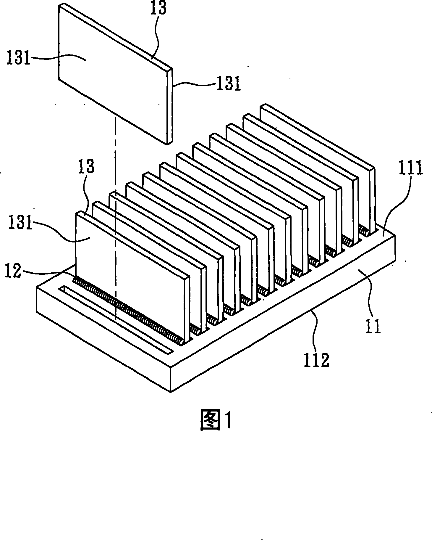
[0004] However, since the heat dissipation fins 13 are welded on the top surface 111 of the base body 11 through the solder 12, and the thermal conductivity of the solder 12 is different from that of the base body 11 and the heat dissipation fins 13, when the heat source is conducted to the heat dissipation fins 13, The solder 12 will cause the loss of heat conduction, making the effect of the heat source conduction to the heat dissipation fins 13 for heat dissipation deteriorated

Method used


Image

  • Method for manufacturing radiator with radiating fins and structure of radiator
  • Method for manufacturing radiator with radiating fins and structure of radiator
  • Method for manufacturing radiator with radiating fins and structure of radiator

Examples


Embodiment Construction

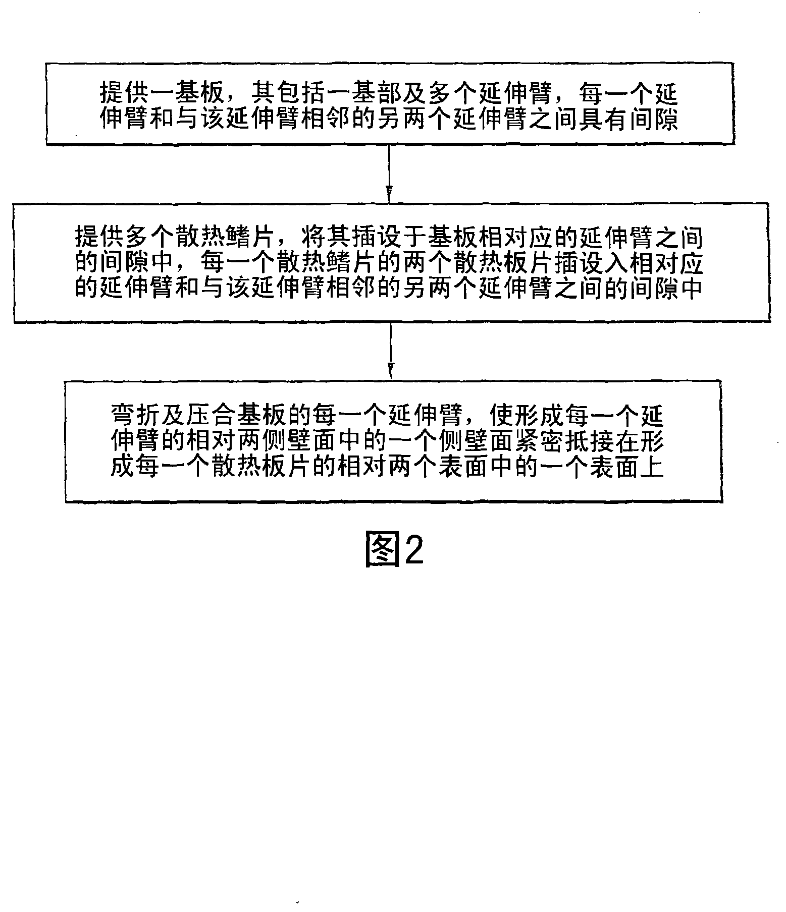
[0031] See Figure 2 to Figure 5 As shown, the present invention provides a method for manufacturing a heat sink and a structure thereof, wherein the manufacturing method includes the following steps:

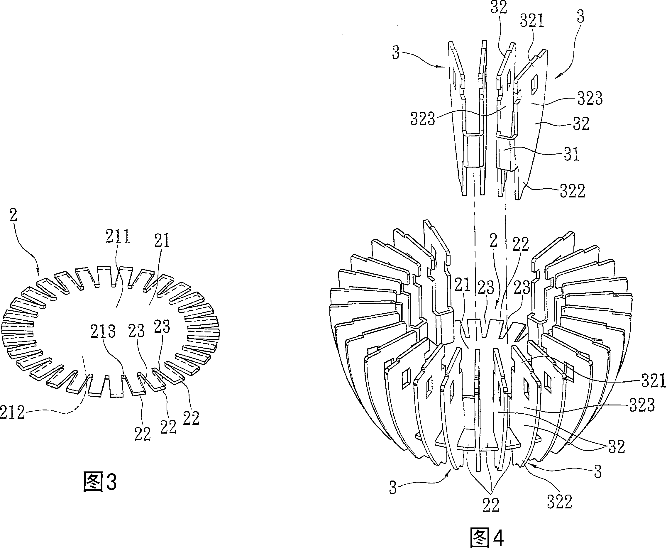
[0032] (1) A substrate 2 is provided, which includes a base 21 and a plurality of extension arms 22. The base 21 has a top surface 211, a bottom surface 212, and side walls 213. The extension arms 22 are spaced apart from the side walls 213 of the base 21 Extending and forming, each extension arm 22 has a gap 23 between the other two adjacent extension arms 22.

[0033] (2) Provide a plurality of heat dissipation fins 3 and insert them into the gap 23 between the corresponding extension arms 22 of the substrate 2, and each heat dissipation fin 3 includes a substrate 31 and is connected to the substrate 31 radiating plates 32 on both sides.

[0034] Wherein, the two heat dissipation plates 32 of each heat dissipation fin 3 are inserted into the gap 23 between the corresponding extensi...


PUM


Abstract

The invention relates to a method for manufacturing a radiator with radiating fins and a structure of the radiator, wherein the manufacturing method comprises the following steps: providing a substrate which comprises a base and a plurality of extending arms, and making clearance exist between each extending arm and other two extending arms adjacent to the extending arm; and providing a pluralityof radiating fins, and inserting the radiating fins into the clearance between the extending arms corresponding to the substrate, wherein each radiating fin comprises a base sheet and two heat sinks,and the two heat sinks of each radiating fin are inserted into the clearance between the corresponding extending arm and the other two extending arms adjacent to the extending arm; and bending and pressing Each extending arm of the substrate to make one side wall surface of both opposite side wall surfaces forming each extending arm closely butt against one surface of both opposite surfaces forming each heat sink. The method has the advantage of avoiding losing thermal conduction.

Description

Technical field [0001] The invention relates to a method for manufacturing a radiator with radiating fins and a structure thereof, in particular to a method for manufacturing a radiator with radiating fins and a structure for welding the radiator fins without using solder. Background technique [0002] Heat sinks are widely used. They are generally used in electronic components that generate heat (such as CPU) or lamps (such as halogen, LED lights) to assist in heat dissipation. Among them, heat sinks with heat dissipation fins are used. The most common, figure 1 Shown is a known heat sink, which uses solder 12 on the top surface 111 of the base body 11 and uses reflow to fix a plurality of heat dissipation fins 13 arranged side by side and equidistantly on the top of the base body 11. 面111上. [0003] The purpose of the heat dissipation fins 13 is to greatly increase the heat dissipation area, contact the heat source through the bottom surface 112 of the base body 11, and then quic...

Claims


Application Information

Patent Timeline
Patent Type & Authority Patents(China)
IPC IPC(8): B21D53/04H05K7/20H01L23/34H01L23/367
Inventor 魏文珍
Owner NENG TYI PRECISION INDS
Learn More