
Connection device for LED lamp and radiating fins

A technology of heat dissipation fins and LED lamps, which is applied to lighting devices, components of lighting devices, cooling/heating devices of lighting devices, etc., which can solve the problems of inability to accurately and effectively control, poor heat dissipation effect, and increased material cost of the outer ring body Processing costs and other issues, to achieve the effect of excellent thermal conductivity, good stability, high mechanical strength

Inactive Publication Date: 2009-08-26
ABLECOM TECH
View PDF0 Cites 18 Cited by
  • Summary
  • Abstract
  • Description
  • Claims
  • Application Information

AI Technical Summary

Problems solved by technology

[0003] In the Taiwan No. 096209554 patent case for the heat dissipation device of the LED light-emitting module previously created by the inventor, in order to improve the stability of the overall connection of the heat dissipation fins, the upper and outer sides of the heat dissipation fin group are embedded with a metal outer surface. Although the ring body clamps the overall shape of the heat dissipation fin group, it increases the material cost of the outer ring body and the processing cost during connection, and the heat dissipation is caused by the inability to accurately and effectively control the distance between each adjacent fin group. poor effect

Method used


Image

  • Connection device for LED lamp and radiating fins
  • Connection device for LED lamp and radiating fins
  • Connection device for LED lamp and radiating fins

Examples


Embodiment Construction

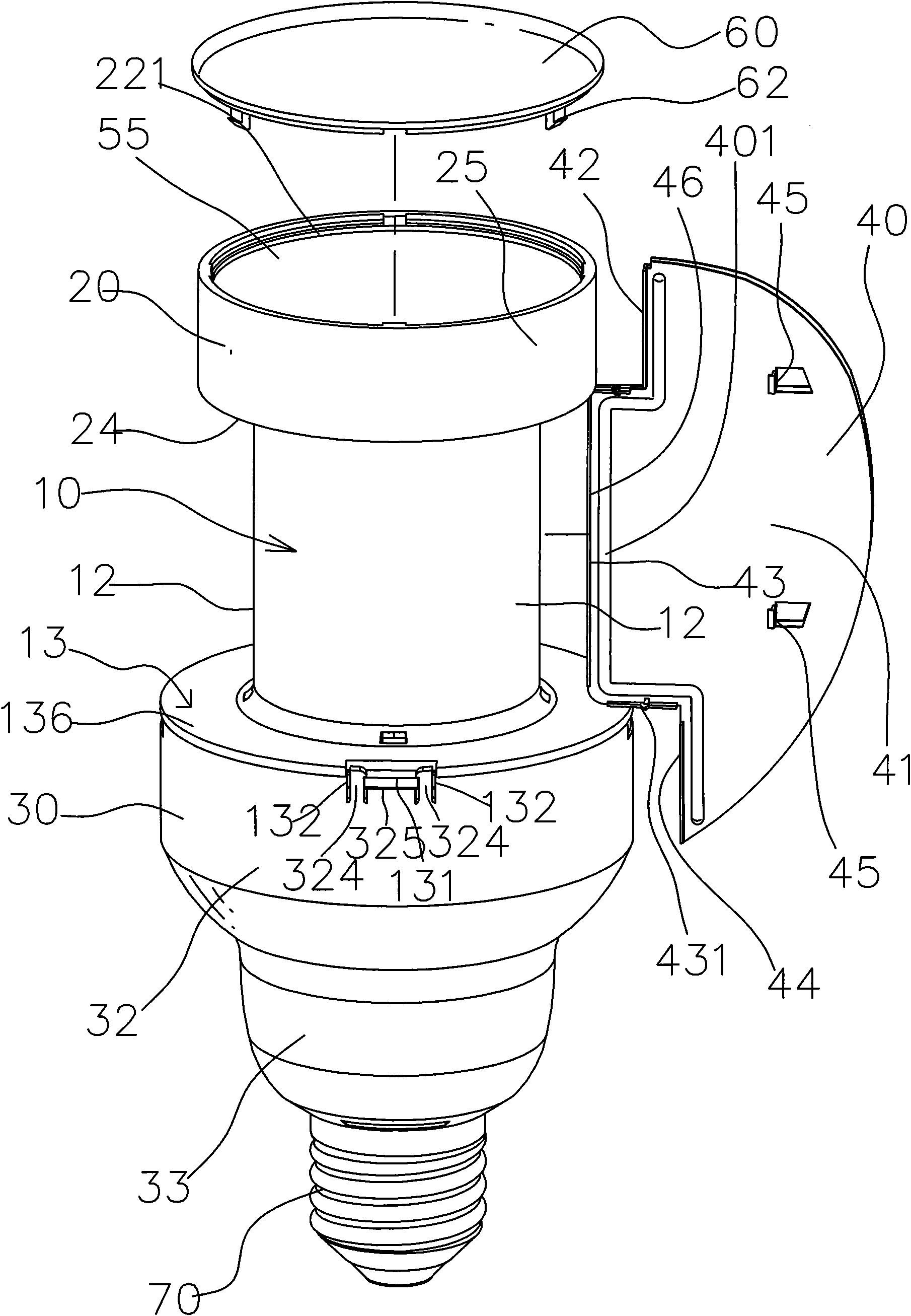
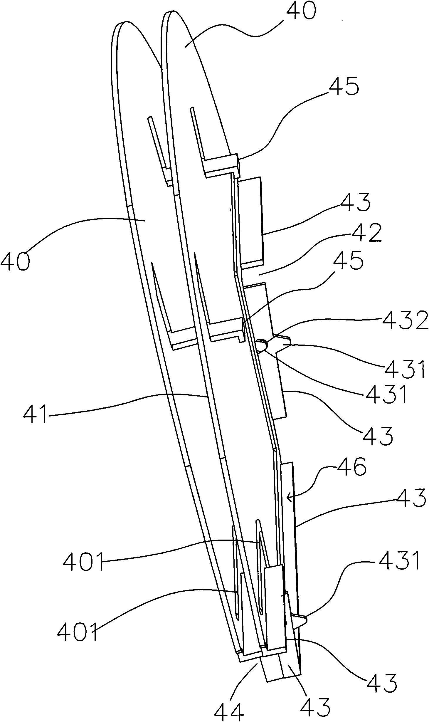
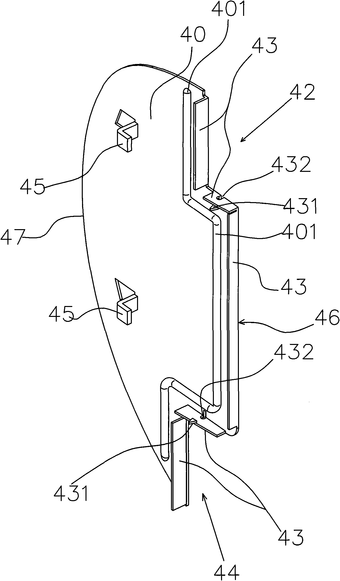
[0026] Such as figure 2 As shown, a plurality of heat dissipation fins 40, (40), the fin fastening device 431 of each fin 40 is inserted into the socket 432 of the adjacent fin 40, and the surface of each fin 40 is set in the form of The L-shaped convex body 45 presses on the surface 41 of the adjacent fin 40, so that the adjacent fins 40, (40) not only have the stability of the connection, but also have equidistant gaps, so that the heat dissipation space is even, so that Improve heat dissipation.

[0027] Such as Figure 4 As shown, it is a three-dimensional exploded view of the parts of the present invention, wherein the circuit board 52 of the LED lighting device 50 is screwed and fixed on the lamp holder 20 and the top surface 11 of the central tube body 10 by bolts 521, so that the lamp holder 20 is fixed on the top surface 11 of the central tube body 10. On the top surface 11 of the central pipe body 10, the lower part of the central pipe body 10 is integrally formed...


PUM


Abstract

The invention discloses a connection device for an LED lamp and radiating fins, which comprises a central tube and a plurality of the radiating fins, wherein the central tube takes the central tube as a center; the upper part of the central tube is connected with an annular lamp holder, while the lower end is connected with a lower shell; the plurality of the radiating fins are connected to the surfaces of the lamp holder, the central tube and lower circular pieces of the central tube; the fin body of each radiating fin is at least punched with more than one convex body; each convex body is pressed against one surface of the adjacent radiating fin; and the adjacent radiating fins contact by means of support of the convex body to enhance the stability, the stress strength and the thermal conductivity of all radiating fins and ensure that the adjacent radiating fins keep constant space.

Description

technical field [0001] The invention relates to a connection device between an LED lamp and a heat dissipation fin, in particular to a connection device for a heat dissipation fin group that is stably connected and can fix the heat dissipation fin without adding other outer ring elements. Background technique [0002] According to the existing LED lamps, a typical example is the patent case of LED projection light source module No. M 297441 of Taiwan New Model Certificate. The heat dissipation unit is composed of multiple fins. Patent scope item 19 and its Figure five , six Disclosed: the heat dissipation fins are provided with a top fold, a bottom fold and an outside fold in three different directions on the side close to the main body, and a fixed edge is provided on the top fold and the bottom fold The holes are matched with the outer edges of the top flange and the bottom flange to extend with a fixed end. Since the fixed end of each adjacent fin is on the inner side...

Claims


Application Information

Patent Timeline
IPC IPC(8): F21V29/00F21V17/00H01L23/367F21Y101/02F21V29/503F21V29/74F21Y115/10
CPCF21K9/00F21K9/1375F21Y2101/02F21V29/2231F21V29/773F21K9/23F21Y2115/10
Inventor 梁见国
Owner ABLECOM TECH
Learn More