High voltage automobile power cell

An automotive power battery and high-voltage technology, applied in lead-acid batteries, battery pack components, lead-acid battery construction, etc., can solve problems such as large current charge-discharge voltage drop, restricting the application of high-voltage batteries, and easy corrosion and deformation of grids.

Active Publication Date: 2010-12-29
JIANGSU HUAFU STORAGE NEW TECH DEV
View PDF0 Cites 0 Cited by
  • Summary
  • Abstract
  • Description
  • Claims
  • Application Information

AI Technical Summary

Problems solved by technology

[0002] Ordinary batteries are composed of multiple positive and negative plates separated by separators and placed vertically in the single battery slot. The positive and negative plates in each single battery slot are connected together by parallel welding. A single cell is 2V, three or six cells are connected in series to form a whole battery of 6V or 12V. If 36V or higher voltage is required, multiple batteries need to be connected in series with wires, so that because the inner plate of the battery is vertical The electrolyte in the battery will be stratified and concentration polarization will occur. In the middle and late stages of battery use, the active material on the positive plate will be overcharged and over-discharged due to the high utilization rate. The active material is easy to soften and fall off, and the grid is easy to corrode and deform. , the lower part of the negative plate is prone to sulfation due to the high acid density, which leads to battery failure
Since the high-voltage battery is connected together by multiple 12V, 6V or 2V batteries with wires, the contact resistance increases, and the voltage drop of high-current charging and discharging is large. Many series-connected monomers are prone to appear backward monomers, which will shorten the battery life and cause poor connection. Convenience and potential safety hazards, large footprint and difficult installation, these defects of ordinary batteries have seriously restricted the application of high-voltage batteries in new energy vehicles

Method used


Image

  • High voltage automobile power cell
  • High voltage automobile power cell
  • High voltage automobile power cell

Examples


Embodiment Construction

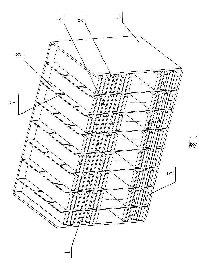
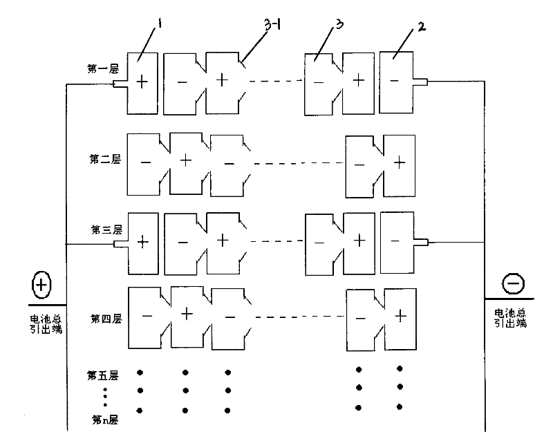
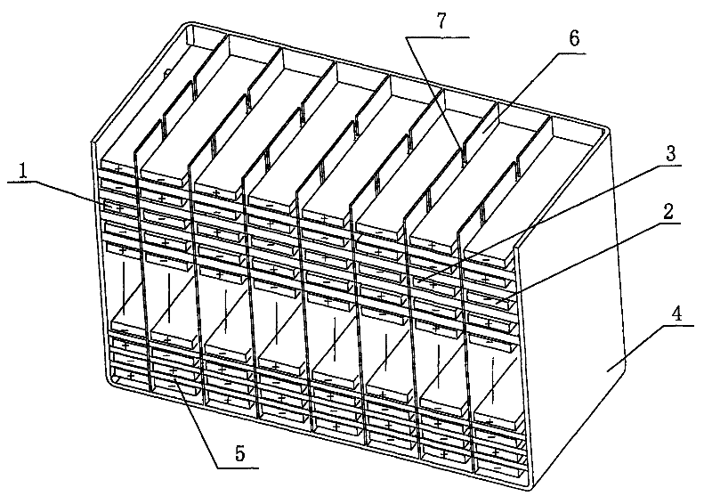
[0008] As shown in Figures 1 and 2, the present invention is made up of housing 4 and three kinds of pole plates, one of which is a positive end pole plate 1, the other is a negative end pole plate 2, and the third is an even number of positive and negative alternating phases, and A continuous pole plate 3 formed by connecting successively through twisted wires 3-1.

[0009] The positive and negative plates are separated in the vertical direction by the porous separator 5 in the casing 4 to form an even number of layers.

[0010] Positive end plates 1 and negative end plates 2 are respectively arranged at both ends of each odd layer, and continuous plates 3 are arranged in the middle, and the plates at both ends of the continuous plate 3 in each odd layer are connected to the corresponding layers The poles of the positive end plate 1 and the negative end plate 2 at the two ends of the structure are opposite to each other, the positive end plate 1, the negative end plate 2 and ...


PUM


Abstract

The invention discloses a high voltage automobile power cell, relating to the technical field of batteries. Even levels are arranged inside a shell by means of porous barriers along the vertical direction; positive end plates, negative end plates and continuous plates are arranged in each odd level, and positive end plates in each odd level are in parallel connection to form a positive outgoing end line, negative end plates in each odd level are in parallel connection to form a negative outgoing end line; continuous plates are arranged horizontally in each even level, and the joints among thecontinuous plates are respectively separated by plastic trough plates on battery shells. The high voltage automobile power cell can realize inter-trough direct connection, shorten the joint distance,reduce the loss of roadlock and voltage drop, and is beneficial for the full implementation of electrochemical reaction, has no concentration polarization caused by electrolyte stratification, has nothreat of active material breakout on the plates, is naturally compressed and can realize high pressure output; wherein, the compression ratio remains constant from start to finish.

Description

technical field [0001] The invention relates to the field of storage battery technology. Background technique [0002] Ordinary batteries are composed of multiple positive and negative plates separated by separators and placed vertically in the single battery slot. The positive and negative plates in each single battery slot are connected together by parallel welding. A single cell is 2V, three or six cells are connected in series to form a whole battery of 6V or 12V. If 36V or higher voltage is required, multiple batteries need to be connected in series with wires, so that because the inner plate of the battery is vertical The electrolyte in the battery will be stratified and concentration polarization will occur. In the middle and late stages of battery use, the active material on the positive plate will be overcharged and over-discharged due to the high utilization rate. The active material is easy to soften and fall off, and the grid is easy to corrode and deform. , The...

Claims


Application Information

Patent Timeline
Patent Type & Authority Patents(China)
IPC IPC(8): H01M10/06H01M10/12H01M10/14H01M10/16H01M2/28H01M50/541
CPCY02E60/126Y02E60/10Y02P70/50
Inventor 曹楚南孙克宁居春山居丽戴德彬
Owner JIANGSU HUAFU STORAGE NEW TECH DEV
Why Eureka
Try Eureka