
Direct current limiting and breaking device based on countercurrent injection method

A technology of reverse current and circuit breaking device, applied in the direction of protection against overcurrent, etc., can solve the problems of complex control, many devices, short breaking time and so on

Inactive Publication Date: 2009-08-26
SOUTHEAST UNIV +1
View PDF0 Cites 21 Cited by
  • Summary
  • Abstract
  • Description
  • Claims
  • Application Information

AI Technical Summary

Problems solved by technology

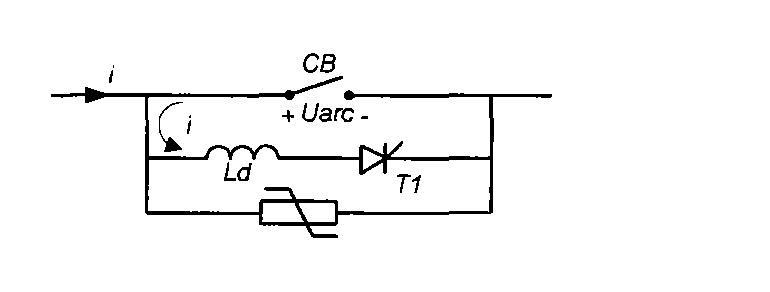
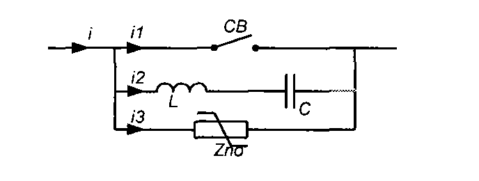
[0015] Compared with the above two DC breaking methods, the reverse current injection method uses more devices, and the control is relatively complicated, but it can break a larger current, and the breaking time is extremely short, especially suitable for those who have problems with the current limiting response time. occasions with higher requirements

Method used


Image

  • Direct current limiting and breaking device based on countercurrent injection method
  • Direct current limiting and breaking device based on countercurrent injection method
  • Direct current limiting and breaking device based on countercurrent injection method

Examples


Embodiment Construction

[0033] A DC current limiting circuit breaking device based on a reverse current injection method, comprising:

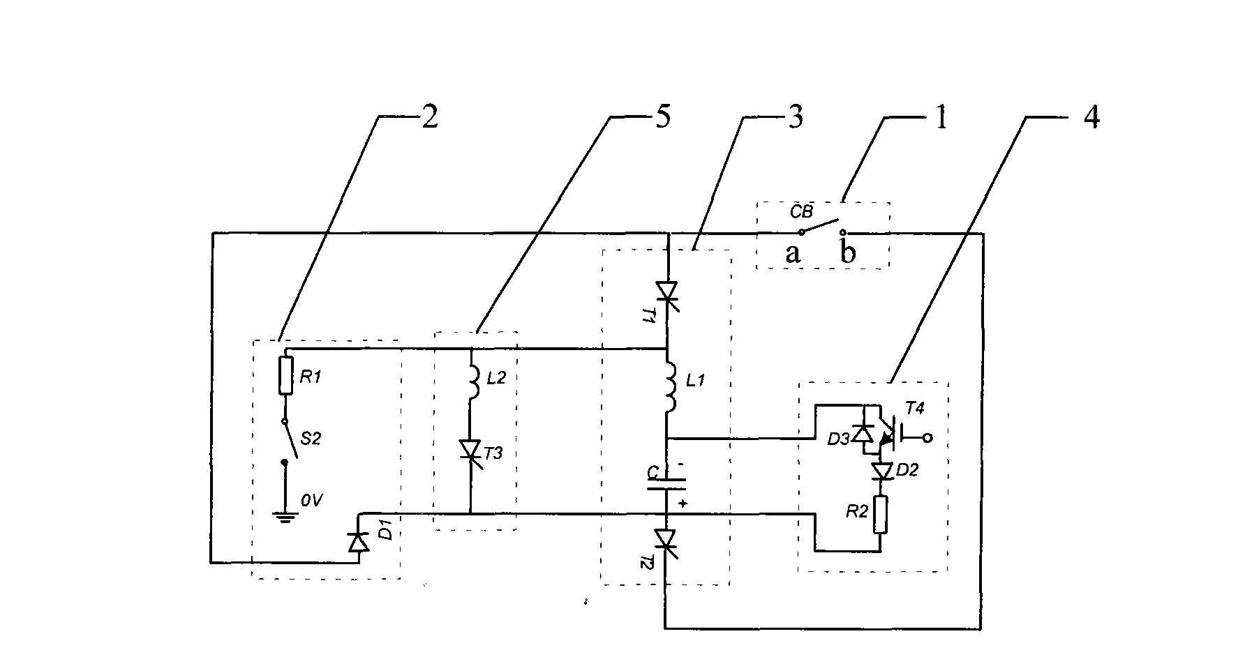
[0034] Circuit breaker for tripping and closing upon receiving an external command 1, pre-charging circuit for capacitors to be directly connected to the busbar 2, reverse current generation circuit for generating reverse current by the voltage charged on the capacitor 3, preventing reverse When the current circuit is working, the absorbing circuit 4 that the voltage on the capacitor is too high and the self-charging circuit 5 that makes the capacitor reverse the voltage on the plate as soon as possible to meet the reclosing requirement, the reverse current generating circuit 3 includes the first inductance L1 An LC circuit composed of a capacitor C in series, the first thyristor T1 and the second thyristor T2 are respectively connected at both ends of the LC circuit, and the cathode of the first thyristor T1 is connected to the first inductor L1 in the LC circuit, an...


PUM


Abstract

The invention provides a direct current limiting and circuit breaking device based on the countercurrent injection method, comprising a circuit breaker, a precharging circuit, a countercurrent generating circuit, an absorbing circuit and a self-charging circuit; wherein, the countercurrent generating circuit comprises an LC circuit which is composed of a first electric inducer and an electric capacitor connected in series and is connected with a first thyristor and a second thyristor respectively at the two ends, the cathode of the first thyristor and the anode of the thyristor are respectively connected with the first electric inducer and the electric capacitor in the LC circuit, the anode of the first thyristor is connected with the a end of the circuit breaker and the cathode of the second thyristor is connected with the b end of the circuit breaker; the self-charging circuit is connected with the LC circuit in parallel; the cathode of the first thyristor is also connected with one end of the precgarging circuit and the other end of the precharging circuit is connected to the ground; a first diode is arranged between the first and the second thyristor, the anode of the second thyristor is connected with the cathode of the first diode and the anode of the first thyristor is connected with the anode of the first diode.

Description

technical field [0001] The invention relates to a direct current limiting circuit breaking device based on a reverse current injection method, which belongs to the field of power transmission and distribution devices. Background technique [0002] Since the AC current has a natural zero-crossing point in each cycle, the arc can be extinguished and the breaking action can be completed when the zero-crossing point is used. However, there is no zero-crossing point for DC current, and an additional arc-extinguishing device must be added in order to extinguish the arc, so that the current is forced to cross zero to achieve breaking. [0003] At present, the commonly used DC breaking methods mainly include: reverse voltage generation method, oscillating current superposition method, and reverse current injection method. details as follows: [0004] ①Reverse voltage generation method [0005] The principle of the reverse voltage generation method is to connect a solid-state swit...

Claims


Application Information

Patent Timeline
IPC IPC(8): H02H3/08
Inventor 梅军郑建勇钟天成
Owner SOUTHEAST UNIV
Learn More