High-efficiency high power factor charger circuit

A high-power, charger technology, applied in battery circuit devices, current collectors, circuit devices, etc., can solve the problems of low cost circuit power factor and increased efficiency, and achieve the effect of improving efficiency, saving electric energy, and improving power factor

Inactive Publication Date: 2009-08-26
SUZHOU INDAL PARK HUABO ELECTRONICS TECH
View PDF5 Cites 10 Cited by
  • Summary
  • Abstract
  • Description
  • Claims
  • Application Information

AI Technical Summary

Problems solved by technology

[0006] The invention provides a charger circuit with high efficiency and high power factor, the purpose of which is to solve the technical problem of low power factor of the existing charger circuit without reducing the efficiency and increasing the cost

Method used


Image

  • High-efficiency high power factor charger circuit
  • High-efficiency high power factor charger circuit
  • High-efficiency high power factor charger circuit

Examples


Embodiment 1

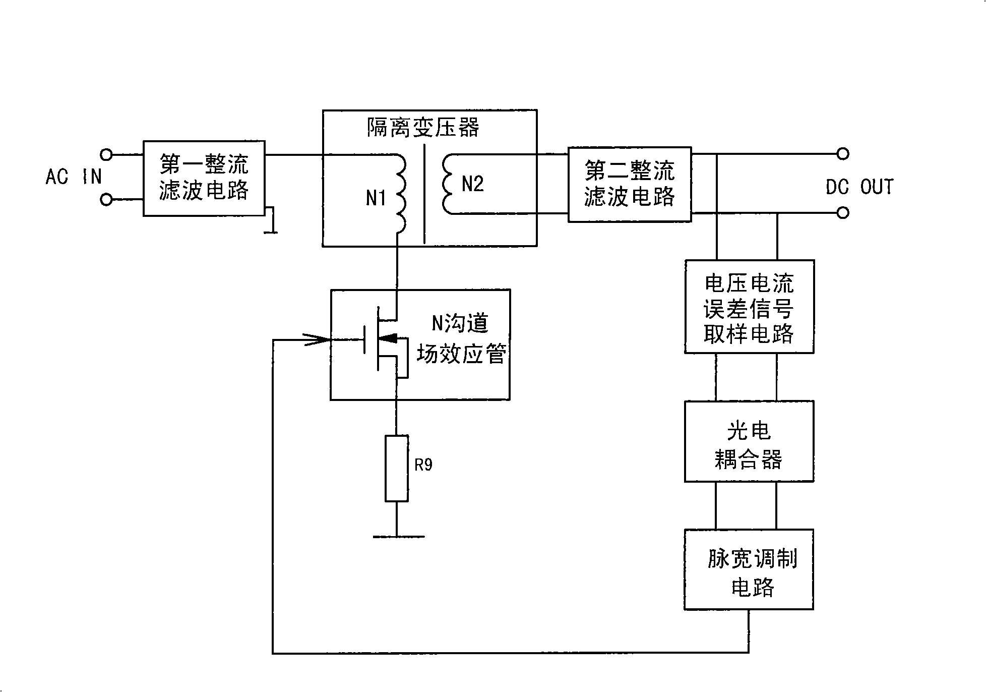
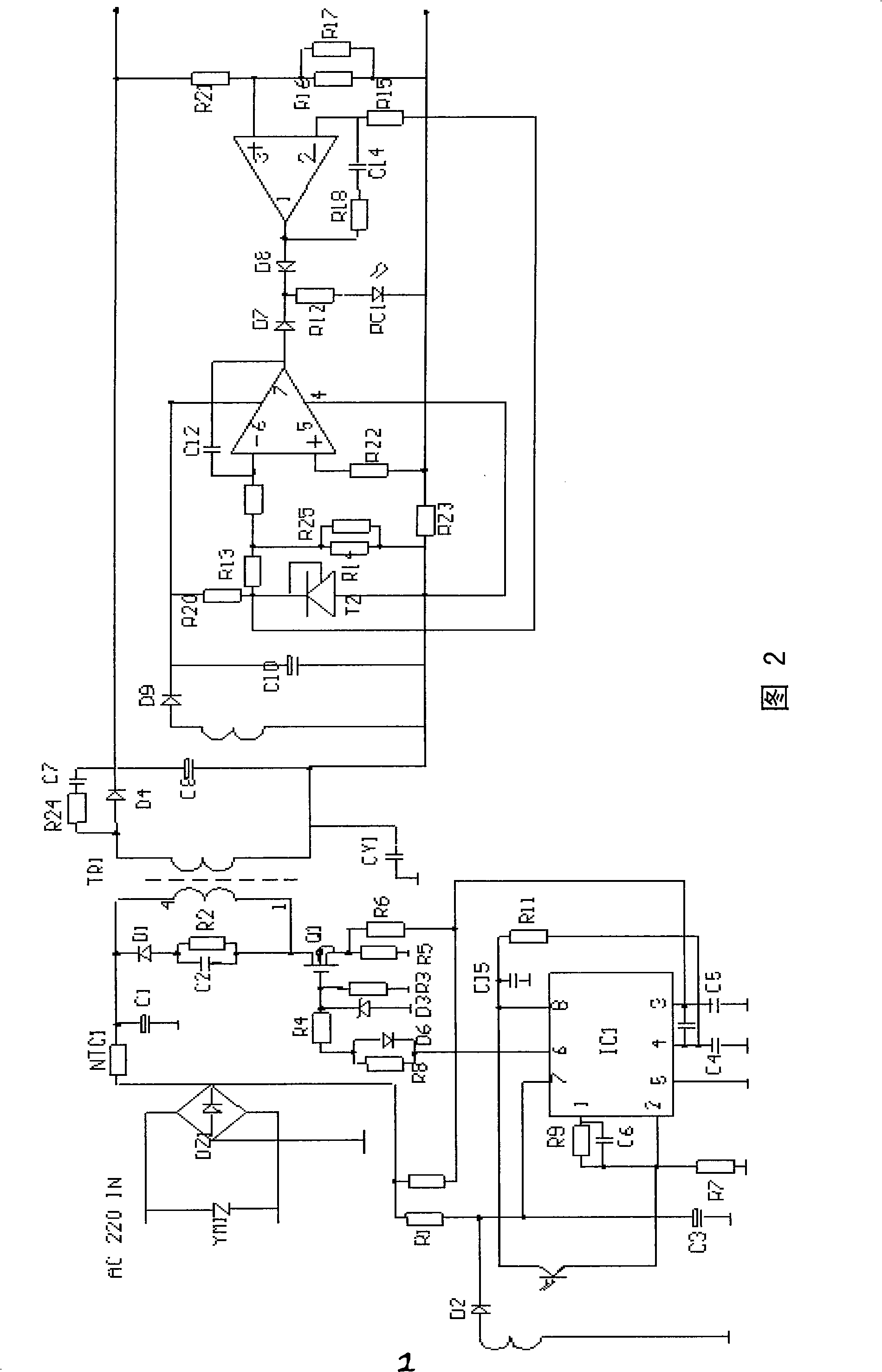
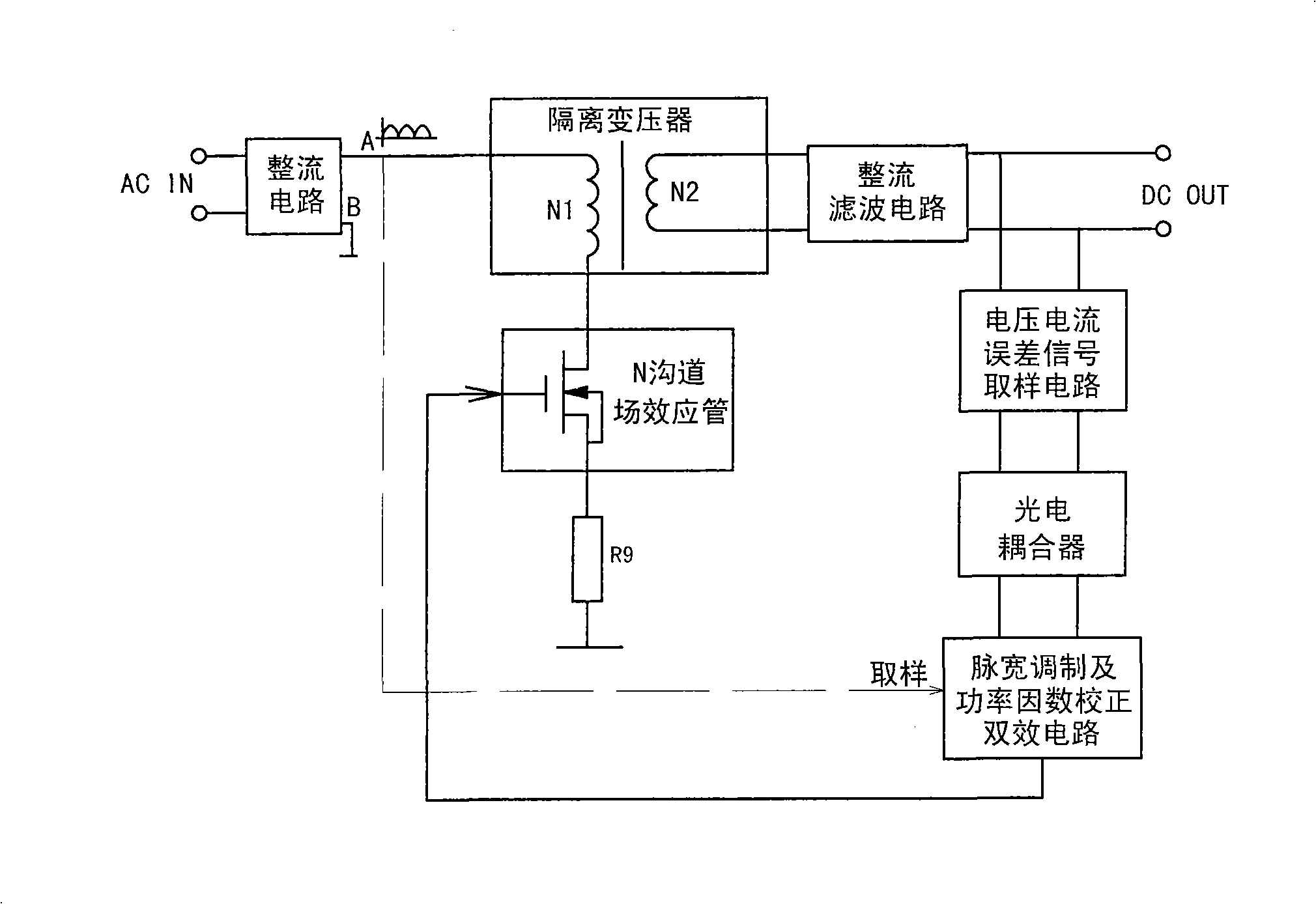
[0031] Embodiment one: see attached image 3 , attached Figure 4 As shown, a charger circuit with high efficiency and high power factor includes a rectifier circuit, a transformer TR1, a rectifier filter circuit, a voltage and current error signal sampling circuit, a photocoupler, a pulse width modulation and power factor correction dual-effect circuit, and an N-channel field field effect transistor Q1.

[0032] The transformer TR1 is a high-frequency transformer, the primary side has one winding which is the first winding N1, and the secondary side has three windings: the second winding N2, the third winding NF and the fourth winding N3. The N-channel field effect transistor Q1 is an N-channel field effect transistor.

[0033] The rectifier circuit is a full-bridge rectifier circuit, and its front part is connected to the AC power frequency power supply through an electromagnetic interference EMI filter link formed by some inductors and capacitors, and its output negative ...


PUM


Abstract

The invention relates to a high-efficiency high power factor charger circuit which comprises a rectification circuit, a transformer, a rectifier filter circuit, a voltage current error signal sample circuit, a photocoupler, a pulse-width modulation circuit and an N slot field-effect transistor; the charger circuit is characterized in that the pulse-width modulation circuit is a double-effect circuit for pulse-width modulation and power factor correction, and is formed by a summit current type boosting power factor correction chip and a chip peripheral circuit. The invention adopts the existing summit current type boosting power factor correction chip at the market and uses the special connecting method, so that the double-effect circuit for pulse-width modulation and power factor correction can be formed and used for replacing the pulse-width modulation circuit in the prior art, thus improving the power factor (being more than or equal to 0.95) of the whole charger circuit on the premise that the cost is not increased and the efficiency is not reduced.

Description

technical field [0001] The invention relates to a storage battery charger, in particular to a circuit of a charger with high efficiency and high power factor. Background technique [0002] In people's life, all kinds of electric tools and electric appliances, such as electric bicycles, are equipped with batteries, so the usage of chargers used in conjunction with these devices is huge. [0003] Existing representative circuits of more advanced and mature chargers, such as figure 1 , figure 2 As shown, it is composed of a first rectification and filtering circuit, a transformer, a second rectification and filtering circuit, a voltage and current error signal sampling circuit, a photocoupler, a pulse width modulation circuit and an N-channel field effect transistor, and the AC power supply is connected to the first rectification and filtering circuit , the output negative end of the first rectification filter circuit is grounded, and its output positive end is connected to ...

Claims


Application Information

Patent Timeline
Patent Type & Authority Applications(China)
IPC IPC(8): H02J7/02H03K7/08H02M1/14H02J7/04
Inventor 郑方耀
Owner SUZHOU INDAL PARK HUABO ELECTRONICS TECH
Why Eureka
Try Eureka