Ecr plasma source

A plasma source, plasma technology, applied in circuits, discharge tubes, electrical components, etc., can solve problems such as hindering electric power coupling, short circuit, limiting coating time, etc.

Inactive Publication Date: 2009-08-26
ROTH & RAU MICROSYST
View PDF1 Cites 17 Cited by
  • Summary
  • Abstract
  • Description
  • Claims
  • Application Information

AI Technical Summary

Problems solved by technology

[0005] In the practical application of this plasma source, its main disadvantage is that some fruitful maintenance measures are required for the discharge chamber
This can lead to a time-dependent influence on the coating result, or rather, limit the possible coating time
[0007] A frequent cause of limiting coating duration is conductive layers that short-circuit the voltage or current leads, or prevent further coupling of electrical power at the coupling window of the electrodeless plasma source

Method used


Image

  • Ecr plasma source
  • Ecr plasma source
  • Ecr plasma source

Examples


Embodiment I

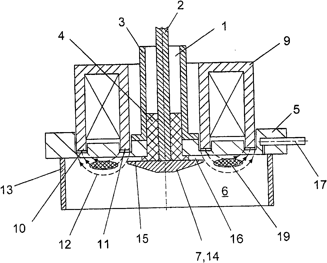
[0021] figure 1 It shows the principle structure of an ECR plasma source proposed by the present invention. The ECR plasma source comprises a coaxial microwave supply line 1 provided with an inner conductor 2 and an outer conductor 3 coaxial with the inner conductor 2 . The inner conductor 2 is insulated from the outer conductor 3 by a dielectric 4 . In this case, the dielectric body 4 simultaneously ensures that the inner conductor 2 is passed through a vacuum flange 5 in an insulated manner, so that the respective ends of the inner conductor 2 protrude freely into the plasma chamber.

[0022] The vacuum flange 5 is designed as a mounting flange, which closes an opening in the wall to the plasma chamber 6 in a vacuum-tight manner.

[0023] The end of the inner conductor 2 , which forms the antenna 7 of the microwave supply line 1 , extends through the vacuum flange 5 and into the plasma chamber 6 . Coaxial to the microwave supply line 1 , outside the plasma chamber 6 there...

Embodiment II

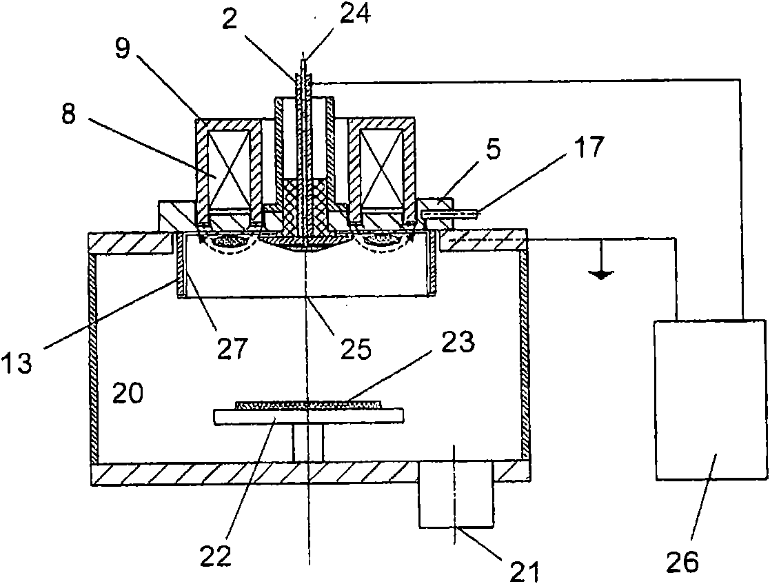
[0029] Belonging to Example II image 3 show a figure 1 The shown ECR plasma source is similar in form of construction, but in a schematic overview there is a coating device which mainly comprises a vacuum chamber 20 equipped with an extraction nozzle 21 and a substrate holder 22, to be processed The substrate 23 can be placed on the support.

[0030] The ECR plasma source proposed according to the invention has a plasma outlet 25 corresponding to the end face of the shield 13 facing away from the vacuum flange 5 , which is arranged parallel to the substrate support 22 .

[0031] In addition to the hole 17 corresponding to Example I, there is also a hole 24 concentrically on the inner conductor 2 . Via these two holes 17 and 24 , carrier and reaction gases can be selectively fed into the vacuum chamber 20 .

[0032] As in embodiment I, the inner conductor 2 and the antenna 7 are insulated in the outer conductor 3 of the microwave supply line 1 . This makes it possible to c...


PUM


Abstract

The invention relates to an ECR plasma source comprising a coaxial microwave supply line (1) with an internal conductor (2) and an external conductor (3), wherein the internal conductor (2) with one end as the antenna (7) passes through a vacuum flange (5) in insulated fashion, which vacuum flange (5) closes off an opening in the wall to the plasma space (6). A multipole magnet arrangement (8) is provided coaxially with respect to the microwave supply line (1) and its magnetic fields pass through the vacuum flange (5) and form an annular-gap magnetic field (12) in the plasma space (6) coaxially with respect to the antenna (7). The antenna (7) protrudes directly into the plasma space (6) and, in comparison with the internal conductor (2), it has a radially larger antenna head (14) at which an underside (15) is provided parallel to the vacuum flange (5) in such a way that an annular gap (16) is formed between the vacuum flange (5) and the underside (15) and that the plasma space (6) is delimited coaxially with respect to the antenna (7) and radially outside the annular-gap magnetic field (12) by means of a shield (13), whose end side facing away from the vacuum flange defines the plasma outlet opening (25).

Description

technical field [0001] The invention relates to an ECR plasma source (electron cyclotron resonance plasma source) according to the preamble of claim 1, in particular for surface treatment in the low pressure range, for example for surface activation, cleaning treatment, substrates abrasion or coating. The ECR plasma source includes a coaxial microwave supply line having an inner conductor and an outer conductor which insulates through a vacuum flange which connects the wall to the plasma chamber One orifice is closed. In addition, the ECR plasma source also includes an antenna, which passes through the vacuum flange as one end of the inner conductor insulated; and a multi-pole magnet device coaxially arranged with the microwave supply line, whose magnetic field passes through the vacuum flange Lan, and form a toroidal magnetic field around the antenna in the plasma chamber. Background technique [0002] According to the prior art, various ECR plasma sources and plasma bea...

Claims


Application Information

Patent Timeline
Patent Type & Authority Applications(China)
IPC IPC(8): H01J37/32
CPCH01J37/32678H01J37/3222H01J37/32192H01J37/32009
Inventor J·马伊V·费尔B·拉乌
Owner ROTH & RAU MICROSYST
Why Eureka
Try Eureka