
Polygon mirror scanner motor and method of manufacturing the same

A manufacturing method, technology of polygonal mirrors, applied in the direction of instruments, mirrors, physical instruments, etc.

Active Publication Date: 2009-08-26
MINEBEA MOTOR MFG
View PDF4 Cites 6 Cited by
  • Summary
  • Abstract
  • Description
  • Claims
  • Application Information

AI Technical Summary

Problems solved by technology

The rotation axis is fixed to the through hole by laser welding

Method used


Image

  • Polygon mirror scanner motor and method of manufacturing the same
  • Polygon mirror scanner motor and method of manufacturing the same
  • Polygon mirror scanner motor and method of manufacturing the same

Examples


Embodiment approach 1

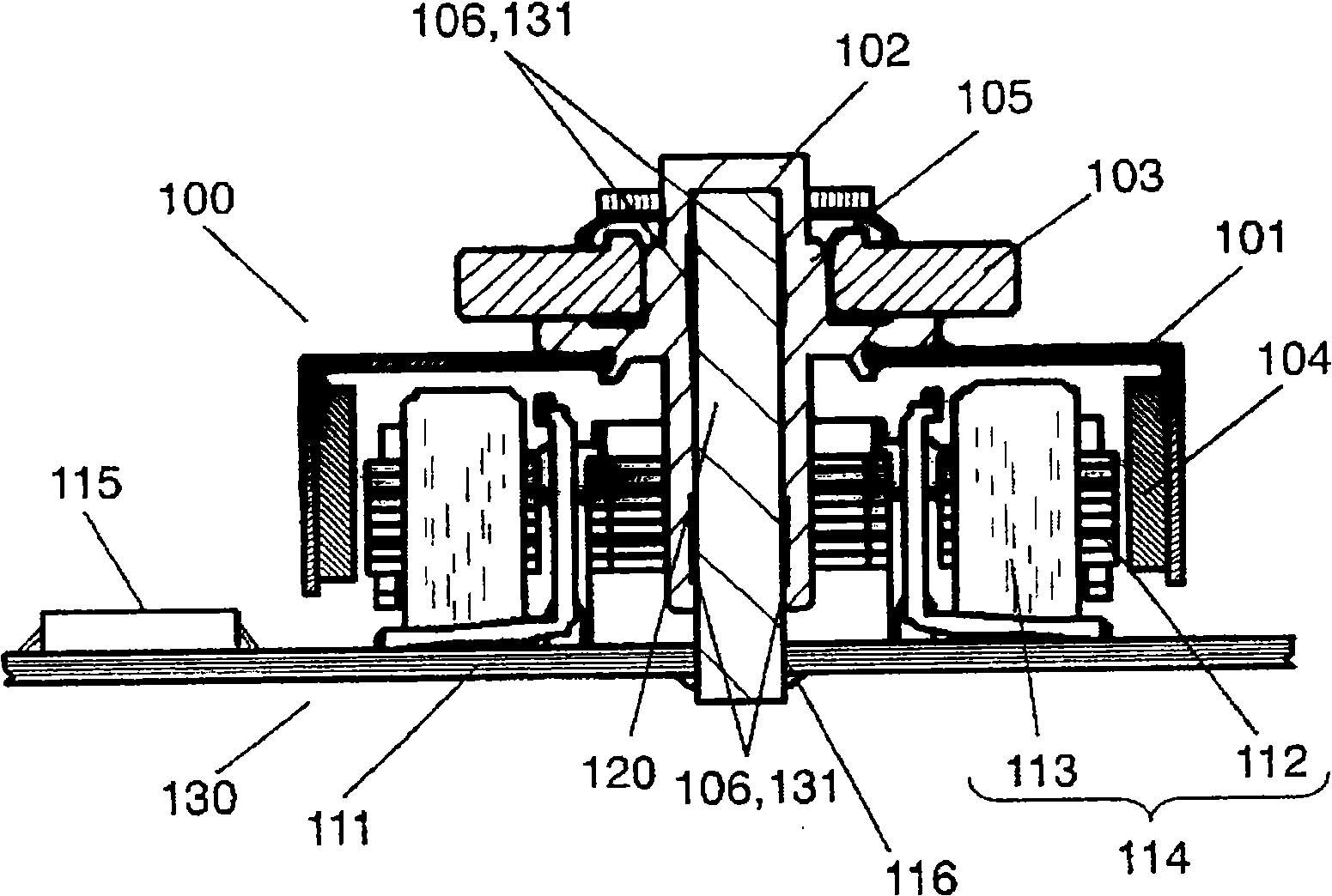
[0087] figure 1 It is a sectional view of the polygon mirror scanner motor according to Embodiment 1 of the present invention. First, refer to figure 1 The main configuration of the polygon mirror scanner motor according to Embodiment 1 of the present invention will be described.

[0088] The polygon mirror scanner motor according to Embodiment 1 includes: a rotor 100 , a winding assembly 114 , a stator 130 , a rotating shaft 120 , and a dynamic pressure bearing 131 . The rotor 100 consists of a rotor frame 101, a rotor magnet 104 attached to the inner wall of the rotor frame 101, a rotor boss 102 having a cylindrical portion 105 and attached to the rotor frame 101, and a polygon mirror (rotary polygon mirror) attached to the rotor boss 102. 103 composition. The winding assembly 114 is composed of a stator core 112 on which magnetic materials are laminated and arranged to face the rotor magnet 104 , and a stator coil 113 wound on the stator core 112 . The stator 130 is c...

Embodiment approach 2

[0109] refer to image 3 A method of manufacturing the polygon mirror scanner motor according to Embodiment 2 of the present invention will be described. image 3 is a cross-sectional view of a jig used in the method of manufacturing a polygon mirror scanner motor according to Embodiment 2 of the present invention.

[0110] The jig 200 includes a fastener 202 for pressing the iron circuit board 111 against the pressing surface 220 of the jig, and a bracket 203 for holding the rotating shaft 120 at right angles to the pressing surface 220 of the jig. The bracket 203 sandwiches and holds the rotating shaft 120 from both sides parallel to the pressing surface 220 of the jig. Furthermore, the jig 200 further includes an opening and closing mechanism (not shown) for opening and closing the bracket, and a moving mechanism (not shown) for moving the fastener 202 up and down in the axial direction.

[0111] The manufacturing method of the polygon mirror scanner motor according to Em...


PUM


Abstract

The rotor of a polygon mirror scanner motor has a rotor magnet fitted to the inner wall of a rotor frame, a rotor boss having a circular tube part and fitted to the rotor frame, and a polygon mirror fitted to the rotor boss. The stator has a stator core formed by layering magnetic substances over each other and disposed so as to face the rotor magnet, a stator coil wrapped around the stator core, and a steel sheet circuit board in which a through hole is formed. A dynamic pressure groove is formed in either one of a shaft secured to the through hole by laser welding and the circular tube part of the rotor boss to thereby construct a dynamic pressure bearing. The circular tube part of the rotor boss is supported by the shaft.

Description

technical field [0001] The present invention relates to a polygon mirror scanner motor equipped with a dynamic pressure bearing device. In particular, it relates to a fixing structure and a fixing method between components requiring high mounting accuracy. Background technique [0002] In recent years, along with the popularization of laser beam printers (hereinafter referred to as "LBP"), polygon mirror scanner motors are required to be further reduced in size, thickness, and cost. At the same time, it is required to reduce rotation fluctuation (jump) and noise. In addition, it is required to maintain high precision for the chamfering of the polygon mirror. [0003] Among them, conventionally, for example, as disclosed in Patent Document 1, a structure in which a bearing is fixed to an iron substrate is used to achieve thinning and cost reduction. In addition, the bearing achieves high precision and long life by using a hydrodynamic bearing, which is a type of dynamic pr...

Claims


Application Information

Patent Timeline
Patent Type & Authority Applications(China)
IPC IPC(8): H02K7/14G02B26/12H02K7/08
CPCG02B26/121H02K7/086H02K7/085F16C2370/12H02K7/14H02K1/187G02B5/09Y10T29/49009
Inventor 福井康嗣角正贵前谷昭光
Owner MINEBEA MOTOR MFG
Features
  • Generate Ideas
  • Intellectual Property
  • Life Sciences
  • Materials
  • Tech Scout
  • Unparalleled Data Quality
  • Higher Quality Content
  • 60% Fewer Hallucinations
Learn More